System for automatically recognizing locations of respective tires

a technology of automatic recognition and respective tires, which is applied in the direction of process and machine control, program control, instruments, etc., can solve the problems of consuming more fuel, reducing fuel efficiency, and entanglement of fuel consumption, so as to achieve a simple and efficient way.

Active Publication Date: 2009-11-26
HYUNDAI MOTOR CO LTD
View PDF6 Cites 18 Cited by
  • Summary
  • Abstract
  • Description
  • Claims
  • Application Information

AI Technical Summary

Benefits of technology

[0015]Accordingly, the present invention has been made keeping in mind the above problems occurring in the prior art, and an object of the present invention is to provide a system for automatically recognizing the locations of respective tires of a vehicle in a simpler and more efficient way.

Problems solved by technology

If the pneumatic pressure of the tire of a vehicle is too high or too low, unfavorable results may entail.
For example, the tire may burst or the vehicle may easily slide, which may cause a terrible accident.
Also, the vehicle may consume more fuel, which may cause a decrease in fuel efficiency.
In addition, the sense of comfort and braking power may decrease.
If the tire temperature is excessively high, a heat separation phenomenon may occur.
However, such a prior art system for automatically recognizing the locations of respective tires using a TPMS has problems in that LFIs are installed on the respective tires, so that costs increase, and in that a large amount of costs for maintenance are required when failures occur on the LFIS.
When both systems are mounted on a vehicle, various wireless communication components should be mounted, so that there are problems in that costs increase and communication errors occur.

Method used


Image

  • System for automatically recognizing locations of respective tires
  • System for automatically recognizing locations of respective tires
  • System for automatically recognizing locations of respective tires

Examples


Embodiment Construction

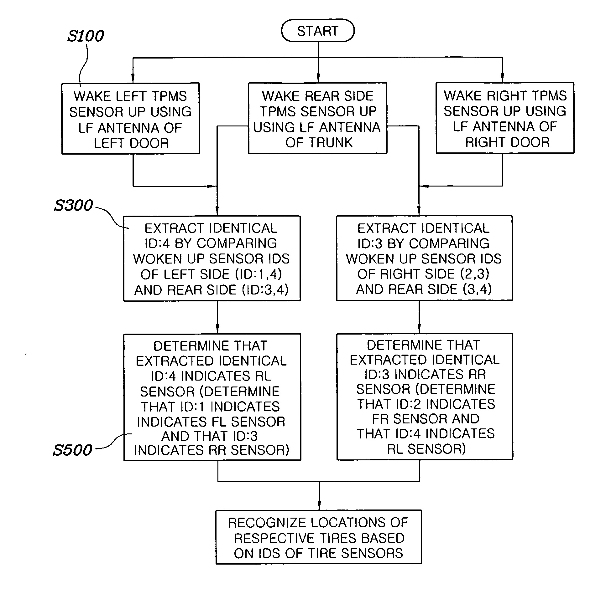
[0026]Systems for automatically recognizing the locations of respective tires according to preferred embodiments of the present invention will be described in detail with reference to the attached drawings, in which the same reference numerals are used throughout the different drawings to designate the same or similar components.

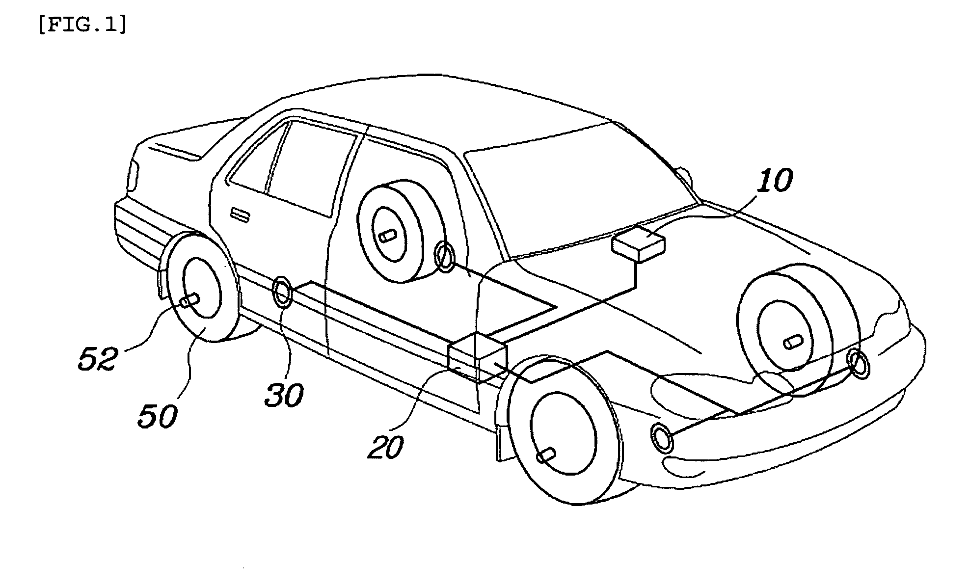
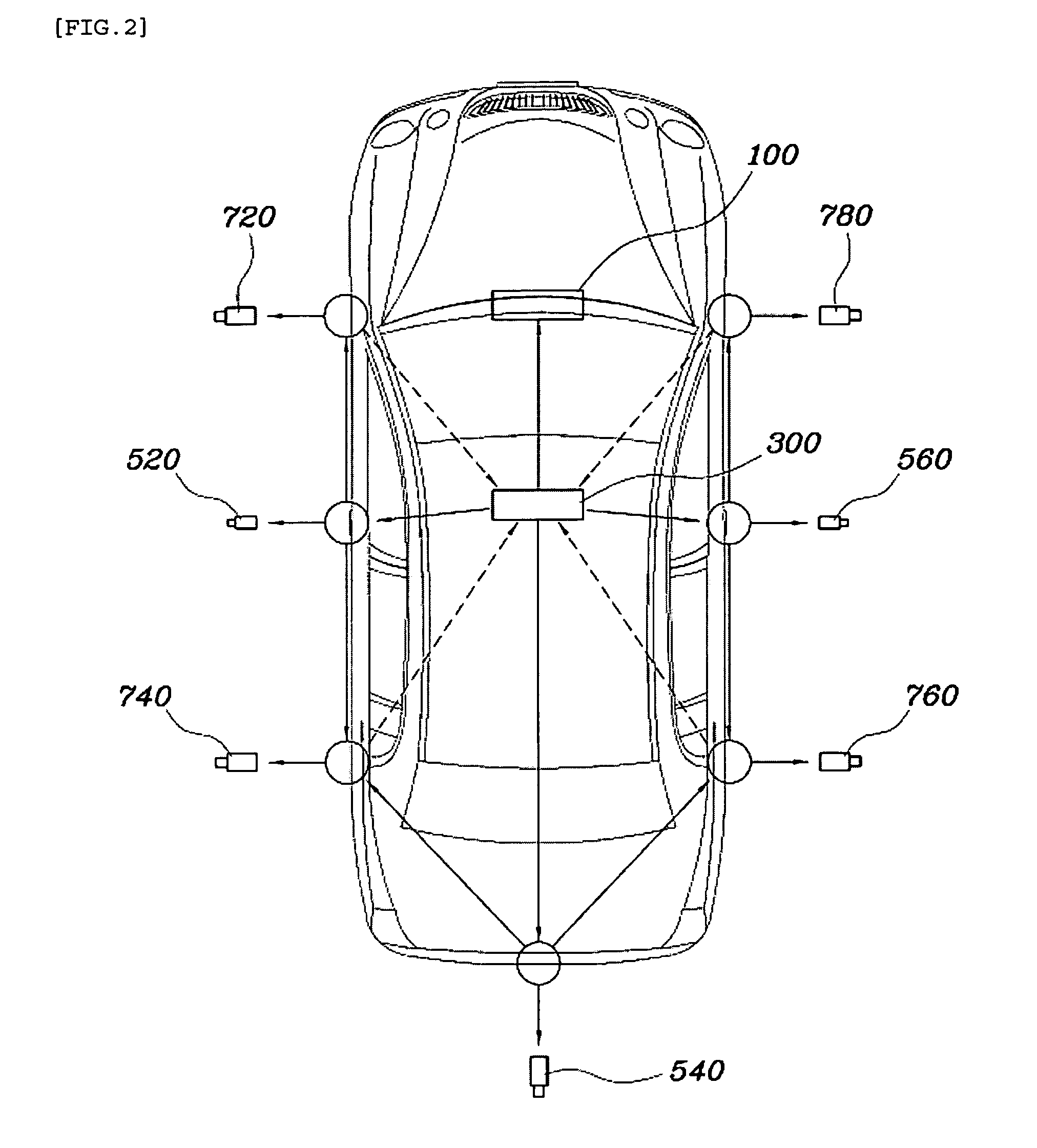
[0027]With reference to FIG. 2, a system for automatically recognizing the locations of respective tires of a vehicle according to an embodiment of the present invention includes tire sensors, startup antennas and a control unit.

[0028]The tire sensors are installed in, on or near the respective tires. They are configured to be able to be woken up in response to startup signals received from the startup sensors and transmit their unique ID signals;

[0029]The startup antennas are installed at or near one of the front and rear sides of the vehicle and both the right and left sides of the vehicle. In response to operation signals received from the control unit, e...


PUM


Abstract

A system for automatically recognizing the locations of respective tires includes tire sensors, startup antennas, and a control unit. Locations of the respective tire sensors can be recognized based information of which antenna is involved and whether signals transmitted are identical. With this system, the locations of respective tires of a vehicle can be recognized in a simpler and more efficient way.

Description

CROSS-REFERENCE TO RELATED APPLICATIONS[0001]This application claims under 35 U.S.C. §119(a) priority to Korean Application No. 10-2008-0046752, filed on May 20, 2008, the disclosure of which is incorporated herein by reference in its entirety.BACKGROUND[0002]1. Technical Field[0003]The present invention relates to a system for automatically recognizing all the locations of the respective tires of a vehicle.[0004]2. Background Art[0005]If the pneumatic pressure of the tire of a vehicle is too high or too low, unfavorable results may entail. For example, the tire may burst or the vehicle may easily slide, which may cause a terrible accident. Also, the vehicle may consume more fuel, which may cause a decrease in fuel efficiency. Further, the lifespan of the tire may be reduced. In addition, the sense of comfort and braking power may decrease. In particular, if the tire pneumatic pressure is low, a hydroplane phenomenon and a standing wave phenomenon may occur. If the tire temperature ...

Claims


Application Information

Patent Timeline
Patent Type & Authority Applications(United States)
IPC IPC(8): B60C23/00
CPCB60C23/0416B60C23/02B60C23/0444B60C23/0471B60C23/0488G05B2219/25308
Inventor KIM, YOU KEUN
Owner HYUNDAI MOTOR CO LTD
Why Eureka
Try Eureka