Method and apparatus for monitoring for leaks in a stage ii fuel vapor recovery system

a technology of vapor recovery system and detection method, which is applied in the direction of liquid transfer device, fluid tightness measurement, instruments, etc., can solve the problem that the escaping fuel vapor can pose a greater threat to the environmen

Active Publication Date: 2009-12-03
FRANKLIN FUELING SYST
View PDF102 Cites 5 Cited by
  • Summary
  • Abstract
  • Description
  • Claims
  • Application Information

AI Technical Summary

Problems solved by technology

Stage II vapor recovery systems typically are only installed in urban areas where the escaping fuel vapors can pose a greater threat to the environment.

Method used


Image

  • Method and apparatus for monitoring for leaks in a stage ii fuel vapor recovery system
  • Method and apparatus for monitoring for leaks in a stage ii fuel vapor recovery system
  • Method and apparatus for monitoring for leaks in a stage ii fuel vapor recovery system

Examples


case 1

[0053

[0054]In case 1, the pressure starts negative and ends less negative. The static pressure resulted in an R2 that is less than 0.90. This indicates the pressure has saturated. Since the pressure remains in the negative region, it indicates that the system is not leaking, thereby resulting in a POSITIVE.

case 2

[0055

[0056]Case 2 is similar to case 1 except the quiet time ended during the upward movement toward zero. Case 2 resulted in an inconclusive test based solely upon the R2 value because the quiet time ended prematurely. One does not know if the slope would continue through the zero pressure region into the positive region or would flat line in the zero region. Therefore the controller will run the slope calculation, described above.

case 3

[0057

[0058]Case 3 occurs when the ending negative pressure is more negative than the starting negative pressure. It is highly unlikely for a leaking tank to result in a more negative ending pressure from what it started at. There is thus no need for the controller to calculate the R2 for this case because any value of R2 would result in a POSITIVE.


PUM


Abstract

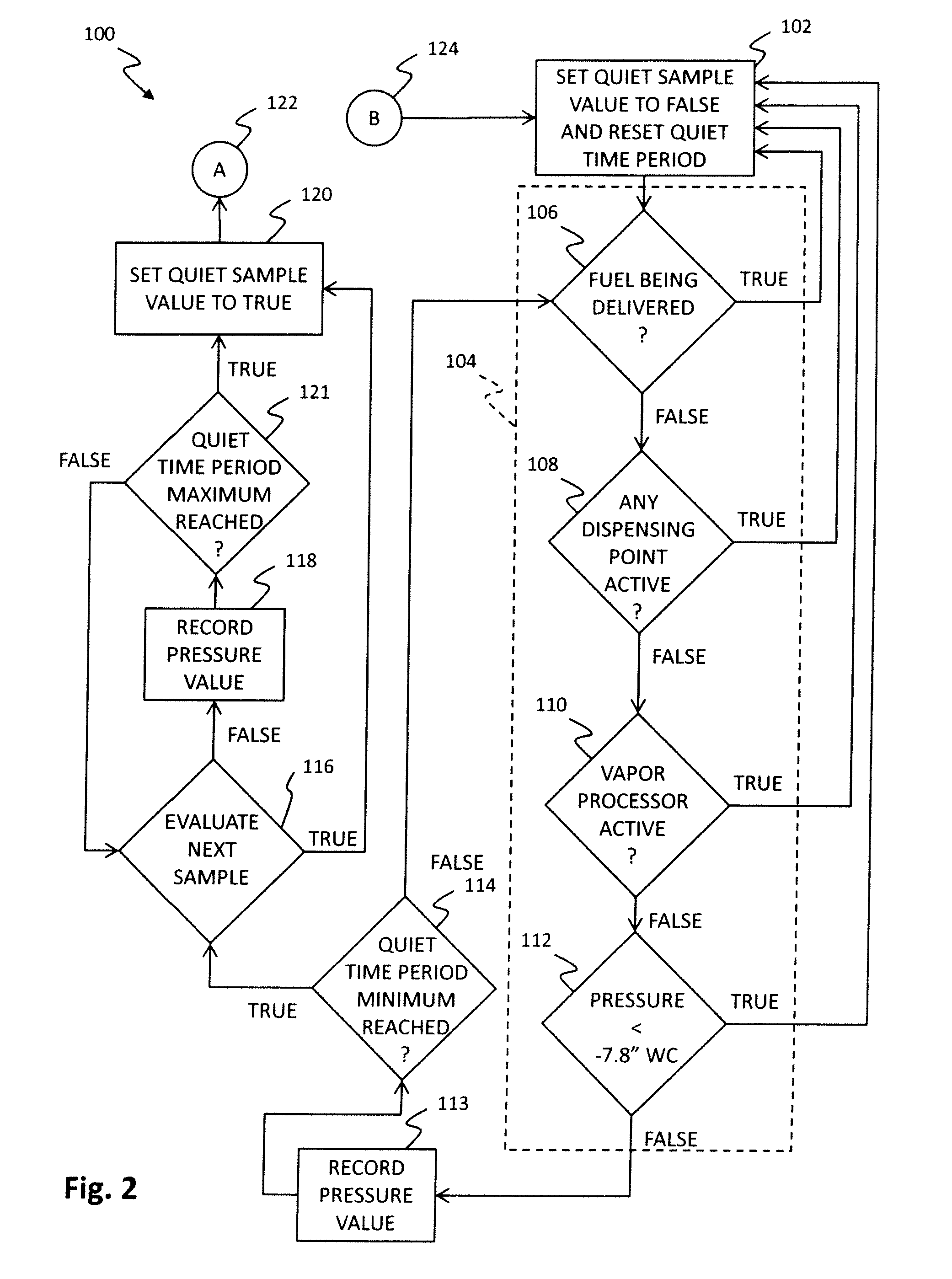
A system and method for detecting a leak in a Stage II vapor recovery system is disclosed. The system may monitor the Stage II vapor recovery system for the occurrence of quiet times and record pressure data during those quiet times. The system may make a determination of a leak based on the evaluation of the pressure data from a plurality of the quiet times.

Description

RELATED APPLICATIONS[0001]This application claims the benefit of U.S. Provisional Patent Application Ser. No. 61 / 056,528, filed May 28, 2008, the entire disclosure of which is expressly incorporated by reference herein.[0002]This application is related to U.S. Provisional Patent Application Ser. No. 61 / 056,522, filed May 28, 2008, the entire disclosure of which is expressly incorporated by reference herein.TECHNICAL FIELD[0003]This invention relates to a method and apparatus for detecting vapor leaks in a Stage II vapor recovery system.BACKGROUND OF INVENTION[0004]Historically as fuel was being dispensed into a vehicle's fuel tank, typically from an underground storage tank (UST), vapor in the vehicle's fuel tank would escape into the atmosphere. In order to prevent this, Stage II vapor recovery systems were developed to collect this vapor and return it to the UST.[0005]Stage II vapor recovery systems recover fuel vapor released from a vehicle's fuel tank as fuel is being dispensed ...

Claims


Application Information

Patent Timeline
Patent Type & Authority Applications(United States)
IPC IPC(8): G01M3/04
CPCG01M3/2892B67D7/0496
Inventor MELLONE, JOSEPH A.BOUCHER, RANDALL S.
Owner FRANKLIN FUELING SYST
Why Eureka
Try Eureka