Corrosion Resistant automatic splice
- Summary
- Abstract
- Description
- Claims
- Application Information
AI Technical Summary
Benefits of technology
Problems solved by technology
Method used
Image
Examples
Embodiment Construction
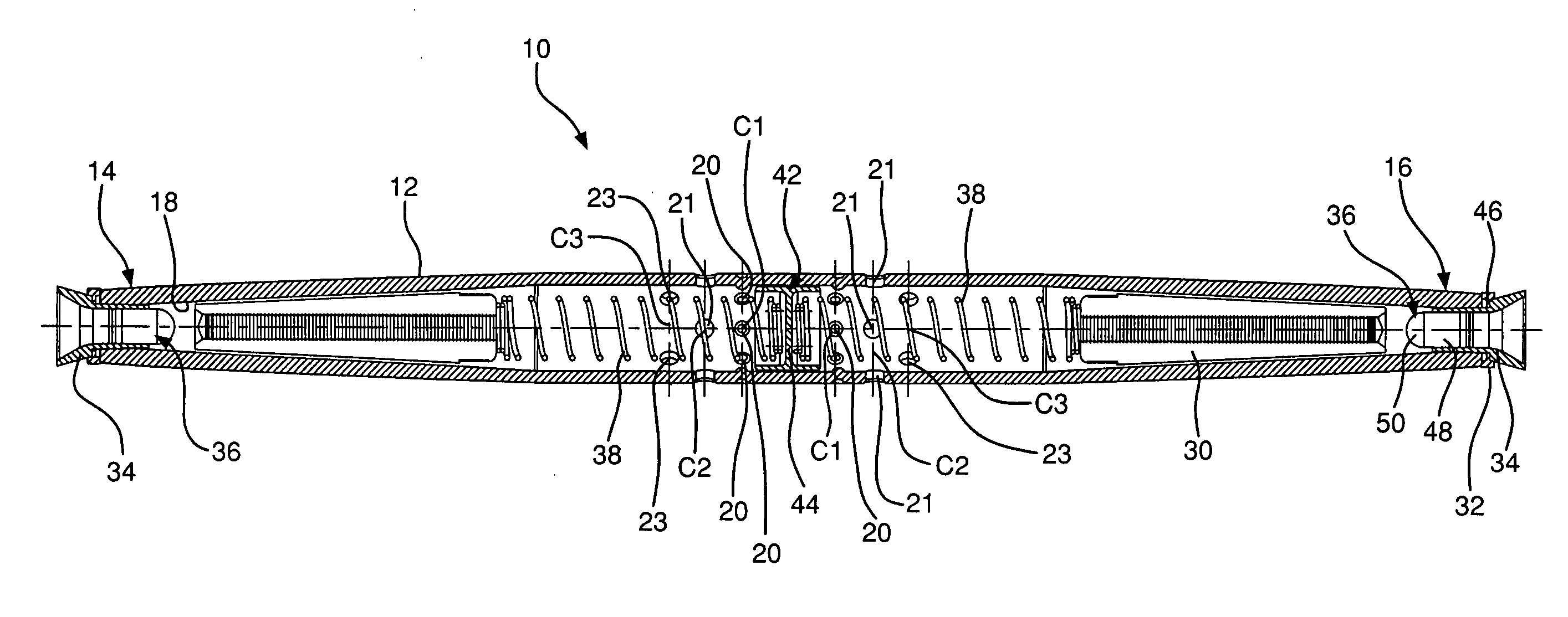
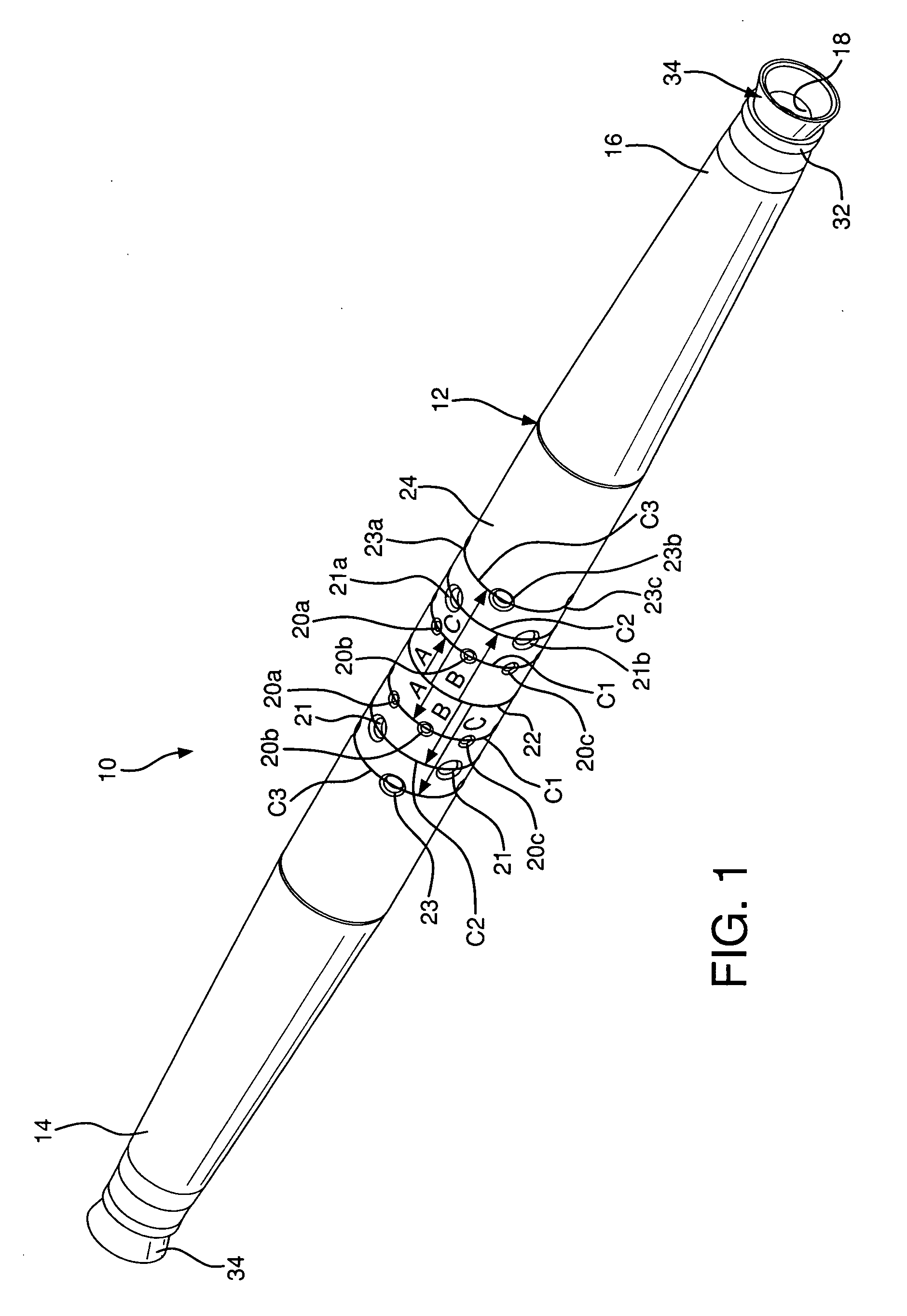
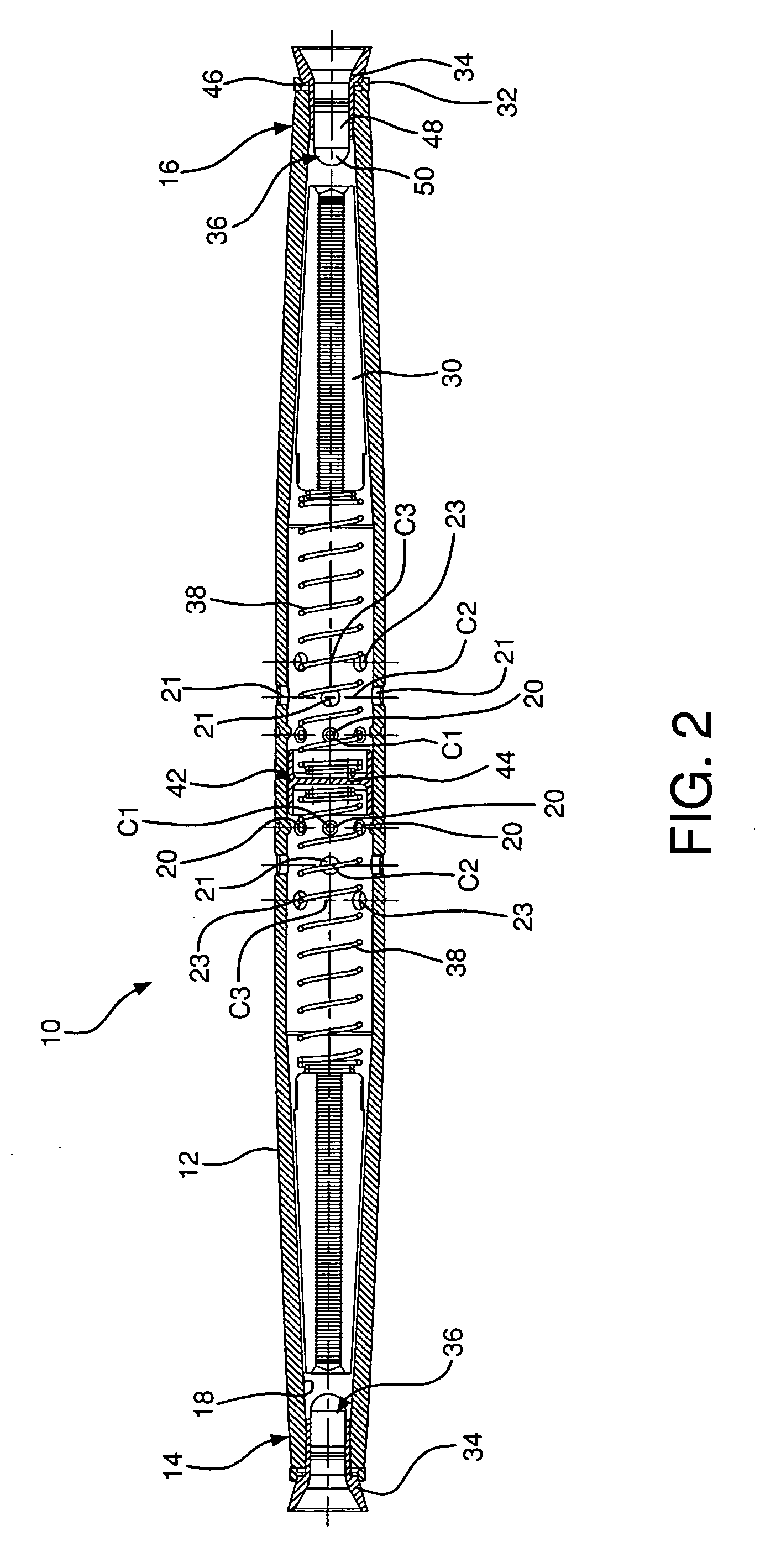
[0031]Turning to FIGS. 1 and 2, a corrosion resistant splice 10 is shown including a housing 12 with a first end 14 and a second end 16, an interior cavity 18 therebetween, a plurality of drainage openings 20, and clamps or jaws 30 at the first and second ends 14, 16 for retaining the cables 40.
[0032]The housing 12 is a tubular body with the first end 14 disposed opposite the second end 16. Both ends are conical and taper away from the center 24 of the splice 10. The center section 24 of the splice 10 is defined by the plurality of drainage openings 20 placed in polar array about the major diameter 22 of the splice body 10. This orientation of the openings 20 concentrated towards the middle of the splice 10 allows for rainwater transporting a majority of contaminants and corrosive elements to exit the splice 10 such that the flushing of rainwater rinses the splice 10.
[0033]By designing the splice 10 in this manner, contaminants flowing from one end 14 or 16 of the splice 10 are purg...
PUM
 Abstract
Description
Claims
Application Information
 - R&D
- Intellectual Property
- Life Sciences
- Materials
- Tech Scout
- Unparalleled Data Quality
- Higher Quality Content
- 60% Fewer Hallucinations
Browse by: Latest US Patents, China's latest patents, Technical Efficacy Thesaurus, Application Domain, Technology Topic, Popular Technical Reports.
© 2025 PatSnap. All rights reserved.Legal|Privacy policy|Modern Slavery Act Transparency Statement|Sitemap|About US| Contact US: help@patsnap.com


