Oscillating energy capture mechanism

a technology of energy capture mechanism and oscillating shaft, which is applied in the direction of working fluid for engines, motors, electrical apparatuses, etc., can solve the problems of interrupting the aquatic life and natural flow of water bodies, and devices are very expensive to build

Inactive Publication Date: 2009-12-10
GARTNER MATTHEW CHARLES
View PDF1 Cites 27 Cited by
  • Summary
  • Abstract
  • Description
  • Claims
  • Application Information

AI Technical Summary

Benefits of technology

[0020]7. The flexible sheet is much less likely to harm birds in wind energy applications, and much less likely to harm aquatic life in hydro energy applications.

Problems solved by technology

These devices are very expensive to build and greatly interrupt the aquatic life and natural flows of water bodies.

Method used


Image

  • Oscillating energy capture mechanism
  • Oscillating energy capture mechanism
  • Oscillating energy capture mechanism

Examples


Embodiment Construction

Preferred Embodiment—FIGS. 1, 2, 3

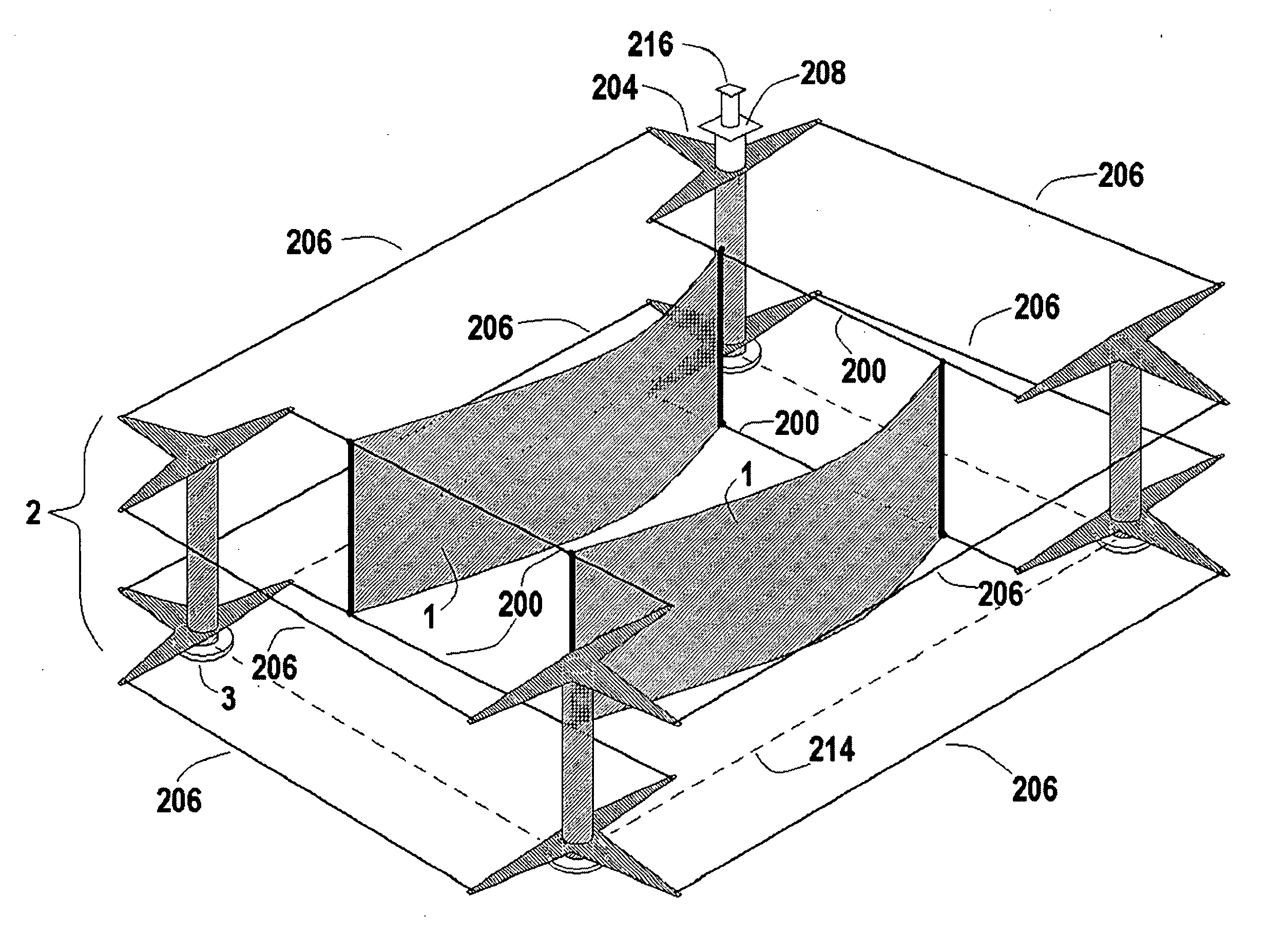
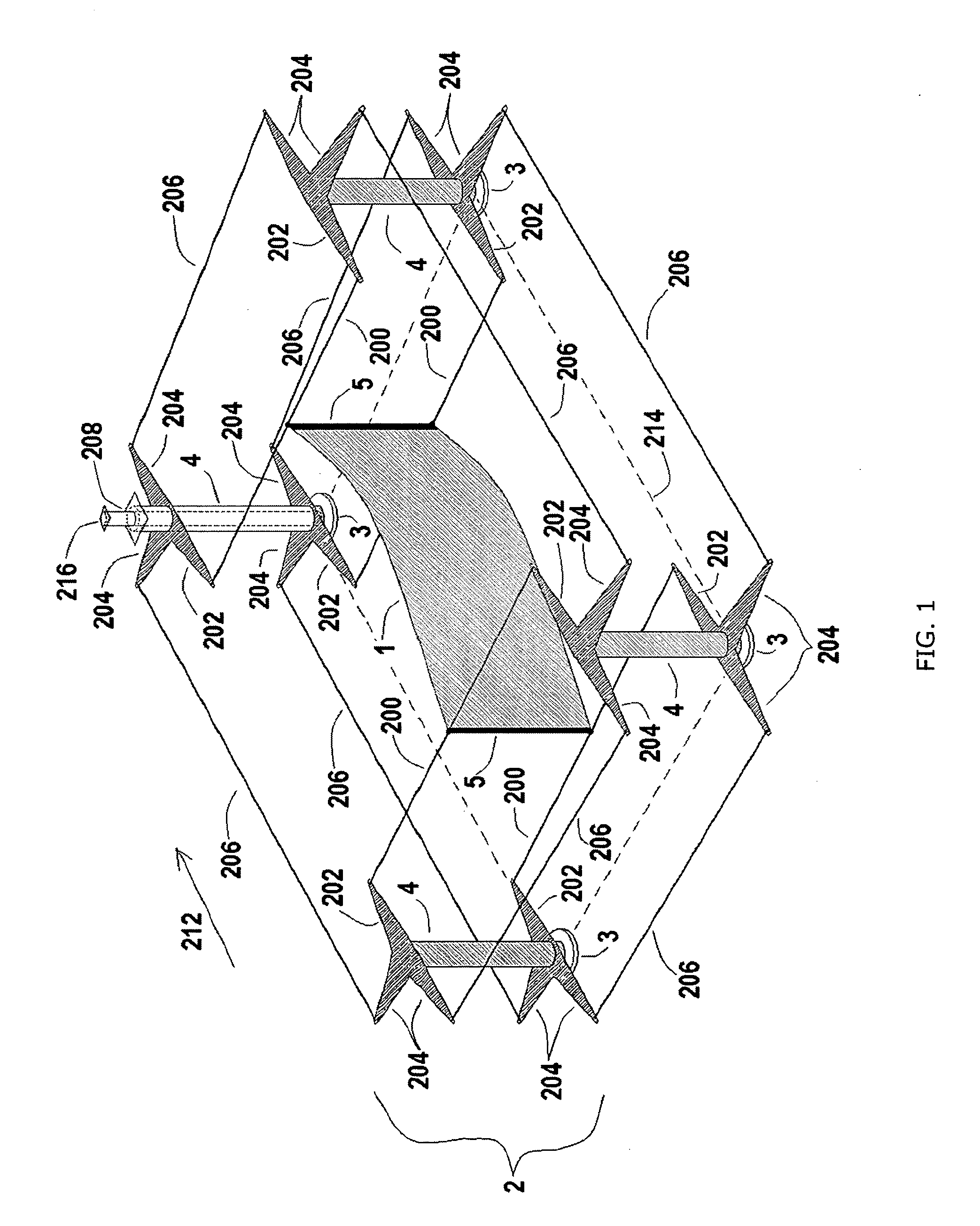
[0023]The perspective view in FIG. 1 shows the invention as utilized within a fluid flow such as a stream, river or other current. Multiple Pivot Mounting Bases 192 are affixed to the ground beneath a fluid flow such as a stream, river or other current. The Pivot Mounting Bases 192 may also be attached to a singular vane-type structure in wind-oriented applications.

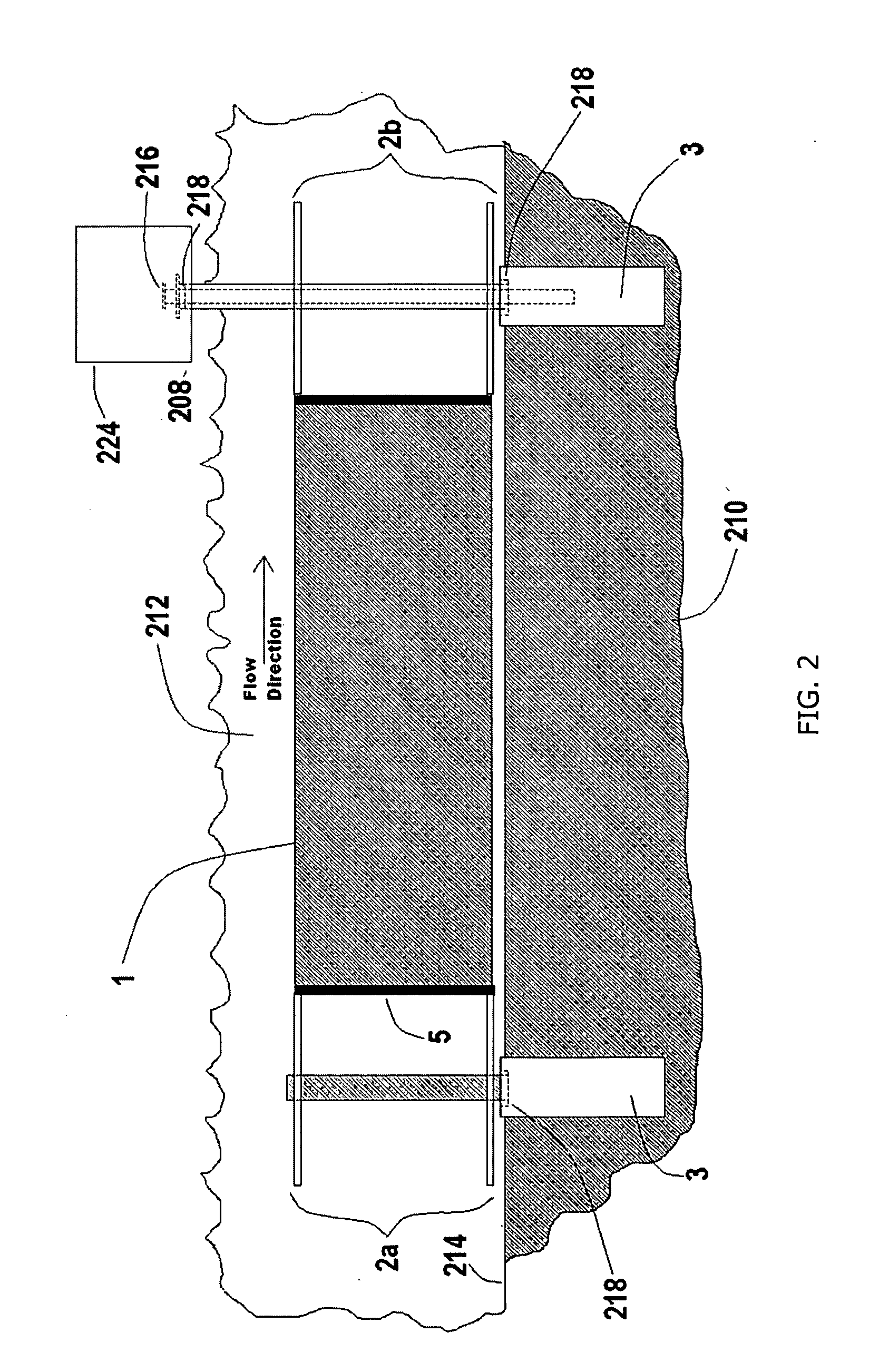
[0024]Pivot Poles 194 are attached to each respective Pivot Mounting Base 192 via a circular Bearing 218 as shown in the side view in FIG. 2. The Pivot Poles 194 are attached perpendicular to the Reference Plane 214 as shown in FIG. 1.

[0025]Each Pivot 190 is composed of a Pivot Pole 194 that has attached to it multiple Suspension Pivot Arms 202 and Connection Pivot Arms 204. The Suspension Pivot Arms 202 and Connection Pivot Arms 204 provide connection points for Suspending Members 200 and Connecting Members 206 as shown in FIG. 1

[0026]The Connection Pivot Arms 204 on each Pivot 190 are c...


PUM


Abstract

Multiple pivots are mounted vertically or horizontally within a rotary or stationary support structure or platform. The pivots are interconnected via members, and between these pivots, a flexible sheet of material is suspended. The mechanism operates via oscillation of a flexible sheet that captures the energy in a fluid flow, and converts it into mechanical motion. The interconnected pivots act in synchronization to vary the angle of attack of the flexible sheet, creating low pressure (lift) areas that impart force into the pivots which then move in an oscillating manner, outputting the energy captured to an energy conversion device. An alternate embodiment makes use of anchors and suspension structures that suspend the entire embodiment in the middle of a fluid flow, and enable remote connection to surfaces not immediately near the location of the device.

Description

CROSS-REFERENCE TO RELATED APPLICATIONS[0001]This application is a continuation-in-part of application Ser. No. 11 / 984,850FEDERALLY SPONSORED RESEARCH[0002]Not applicableSEQUENCE LISTING OR PROGRAM[0003]Not applicableBACKGROUND OF THE INVENTION[0004]1. Field of the Invention[0005]This invention relates to the capture of energy from natural sources such as wind and water. 2. Prior Art[0006]US Patent Documents:U.S. Pat. No. 6,914,345Jul. 5, 2005Webster 290 / 54.U.S. Pat. No. 4,348,594Sep. 7, 1982Lipfert 290 / 54.U.S. Pat. No. 6,153,944Nov. 28, 2000Clark 290 / 54.U.S. Pat. No. 4,476,397Oct. 9, 1984Lawson 290 / 54.U.S. Pat. No. 6,273,680Aug. 14, 2001Arnold 416 / 1U.S. Pat. No. 6,217,284Apr. 17, 2001Lawrence 416 / 83U.S. Pat. No. 7,045,912May 16, 2006Leijon et al. 290 / 42U.S. Pat. No. 4,228,360Oct. 14, 1980Navarro 290 / 43U.S. Pat. No. 2,604,882July 1952Schnacke 123 / 185.4U.S. Pat. No. 6,581,562Jun. 24, 2003Goebel, et al.123 / 185.3U.S. Pat. No. 6,726,440Mar. 22, 2002Pollard 415 / 41U.S. Pat. No. 4,595,336J...

Claims


Application Information

Patent Timeline
Patent Type & Authority Applications(United States)
IPC IPC(8): F03B13/10
CPCF03B17/00Y02E10/20F05B2240/97F05B2210/16
Inventor GARTNER, MATTHEW CHARLES
Owner GARTNER MATTHEW CHARLES
Why Eureka
Try Eureka