Robot joint driving apparatus and robot having the same

Inactive Publication Date: 2009-12-17
SAMSUNG ELECTRONICS CO LTD
View PDF12 Cites 24 Cited by
  • Summary
  • Abstract
  • Description
  • Claims
  • Application Information

AI Technical Summary

Benefits of technology

[0013]Therefore, one aspect of the present invention is to provide a robot joint driving appa

Problems solved by technology

The joint driving method using the speed reducer has problems, such as limited disposition of a driving appara

Method used


Image

  • Robot joint driving apparatus and robot having the same
  • Robot joint driving apparatus and robot having the same
  • Robot joint driving apparatus and robot having the same

Examples


Example

[0037]Reference will now be made in detail to the embodiments of the present invention, examples of which are illustrated in the accompanying drawings, wherein like reference numerals refer to like elements throughout. The embodiments are described below to explain the present invention by referring to the annexed drawings.

[0038]The present invention may be applied to robots having various shapes, but a humanoid robot will be exemplarily described below.

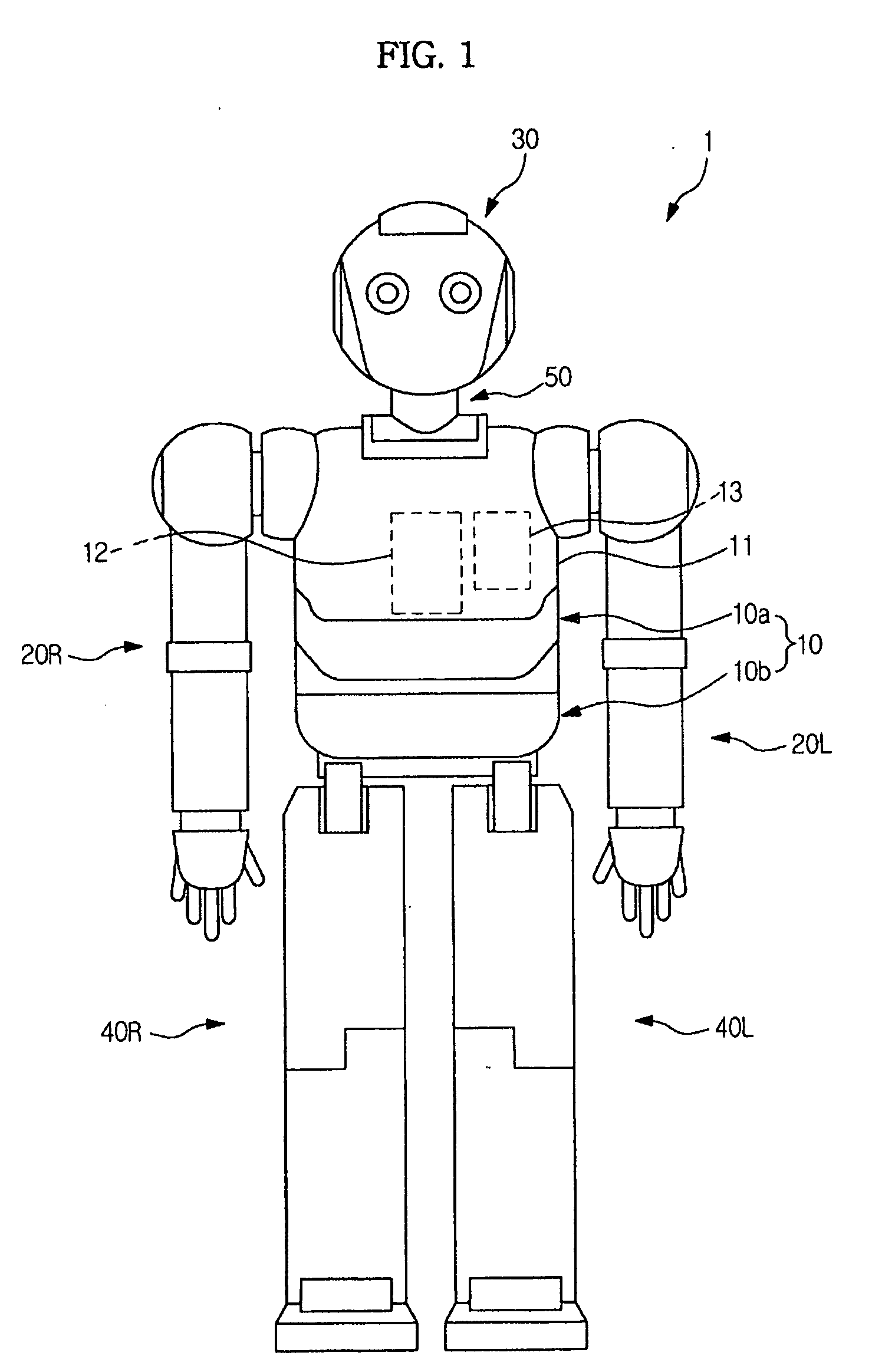
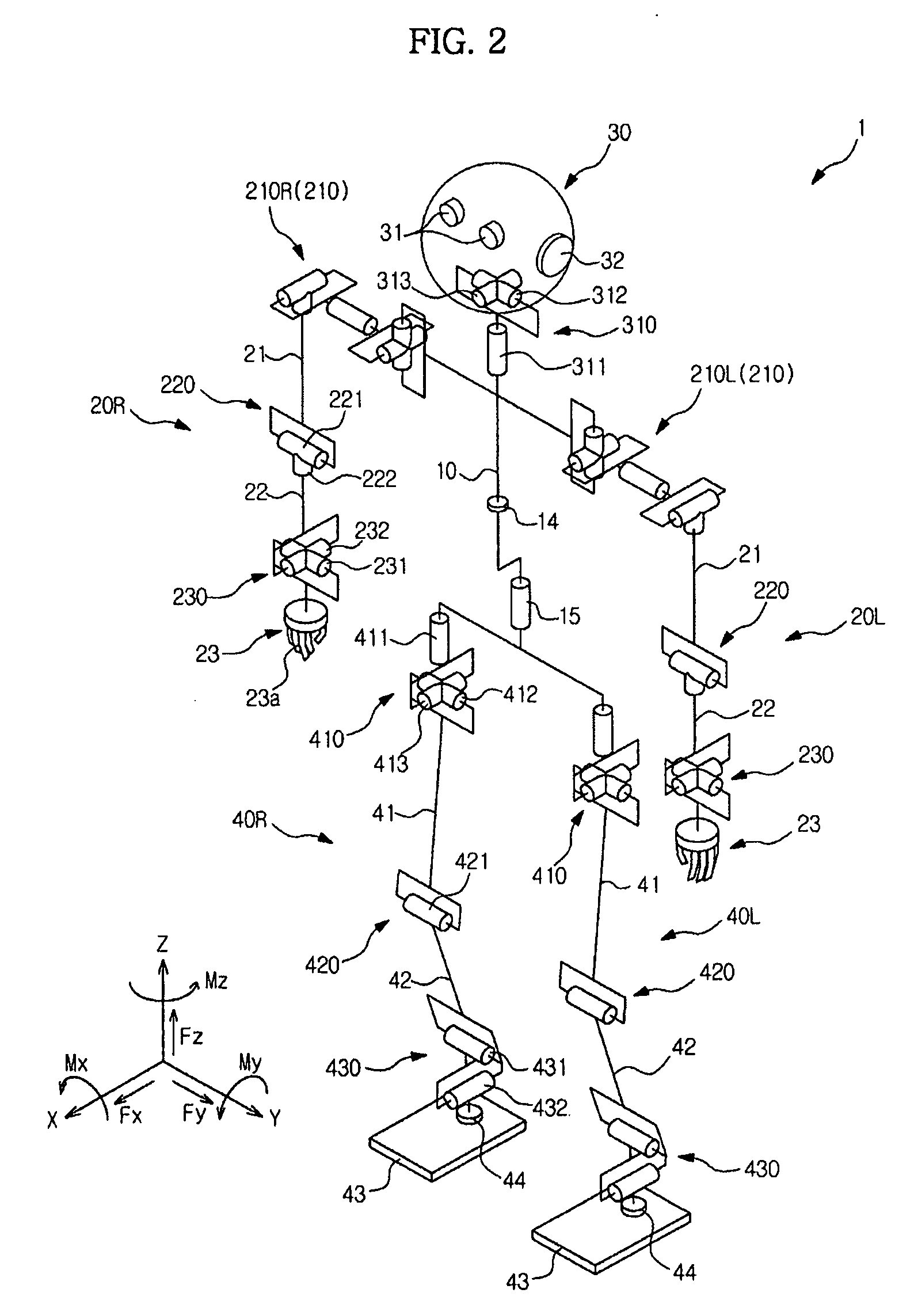
[0039]FIG. 1 is a view illustrating the external appearance of a humanoid robot in accordance with one embodiment of the present invention, and FIG. 2 is a schematic view illustrating the constitution of the humanoid robot of FIG. 1.

[0040]As shown in FIGS. 1 and 2, a humanoid robot (hereinafter, briefly referred to as a ‘robot’) 1 includes a trunk 10, arms 20R and 20L respectively connected to both sides of the upper portion of the trunk 10, a head 30 connected to the upper end of the trunk 10, and legs 40R and 40L respectively conne...


PUM


Abstract

Disclosed are a robot joint driving apparatus and a robot having the same. The robot joint driving apparatus includes a driving motor being rotatable in forward and reverse directions; a pair of movable members connected to the driving motor, and moving rectilinearly in mutually opposite directions according to the rotation of the driving motor; a wire provided with both ends respectively connected to the pair of movable members; and a joint unit, on which the wire is wound, driven by the movement of the wire.

Description

CROSS-REFERENCE TO RELATED APPLICATIONS[0001]This application claims the benefit of Korean Patent Application No. 2008-0054851, filed on Jun. 11, 2008, in the Korean Intellectual Property Office, the disclosure of which is incorporated herein by reference.BACKGROUND[0002]1. Field[0003]The present invention relates to a robot joint driving apparatus and a robot having the same, and more particularly to a robot joint driving apparatus, which has an improved joint driving structure, and a robot having the robot joint driving apparatus.[0004]2. Description of the Related Art[0005]Robots having various shapes, which can carry out biped walking, quadruped walking, etc., have been developed for home, military and industrial purposes.[0006]The above robots perform various motions including a walking motion, such as running or walking, through movement of joints.[0007]Joint driving methods are divided into a joint driving method using a motor and a speed reducer connected to the motor and a ...

Claims


Application Information

Patent Timeline
IPC IPC(8): F16H25/20F16H25/22
CPCB25J9/104B25J17/0241F16H19/06Y10T74/18608F16H2025/2053F16H2019/0695F16H25/20B25J17/00
Inventor YANG, SOO SANGOH, YEON TAEKLEE, YOUN BAEK
Owner SAMSUNG ELECTRONICS CO LTD
Why Eureka
Try Eureka