Cooking Grates and Grills Incorporating Such Grates

a technology of cooking grates and grills, which is applied in the field of cooking grills, can solve the problems of grease fire, damage to the resulting quality of grilled food, and charring of food products being grilled

Active Publication Date: 2009-12-17
CHAR BROIL
View PDF32 Cites 47 Cited by
  • Summary
  • Abstract
  • Description
  • Claims
  • Application Information

AI Technical Summary

Problems solved by technology

A perceived disadvantage with such grills as described is that food drippings, such as liquefied greases and oils, pass through the open spaces in the grate and come into contact with gas flames or hot surfaces during cooking causing flash flames or “flare-ups,” which can result in the charring of the food product being grilled.
Although vaporization of the food drippings is desirable because the vapors enhance the flavor of food cooked on a grill, the flare-ups and flame contact frequently associated with the food drippings can be detrimental to the resulting quality of grilled food.
It should also be noted that tests of this device showed that high temperatures on the top surfaces of the grate bars led to grease fires.
In addition, the grate was very heavy and expensive to manufacture due to the high weight density per square inch of the solid bars.
A perceived limitation of this invention is that a special material or construction is required to prevent warping of the flat surface in close proximity to the vertical ribs.
These vertical ribs function similarly to those in EP 1776028 in terms of reducing combustion of grease drippings in the channel, although the perforated holes limit the effectiveness of this feature by allowing some air to enter the channels from below.
However, this invention has perceived limitations in that the perforated plate is hard to clean and difficult to manufacture, and the grate includes two independent assemblies of substantial complexity.
Similarly, others of the devices reduce the flavor of the cooked food by completely eliminating or reducing the favorable impact of the food drippings.

Method used


Image

  • Cooking Grates and Grills Incorporating Such Grates
  • Cooking Grates and Grills Incorporating Such Grates
  • Cooking Grates and Grills Incorporating Such Grates

Examples


Embodiment Construction

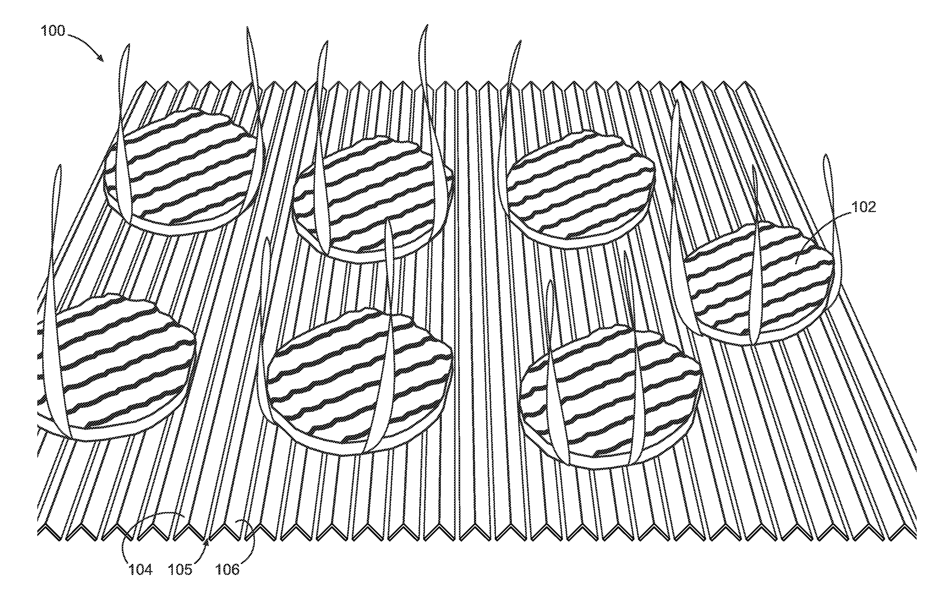
[0027]Cooking grates and grills incorporating such cooking grates are provided that are configured for reducing flare-ups. In this regard, in some embodiments, the cooking grate incorporates elements with narrow gaps between the elements. By way of example, the gaps of some embodiments may be between 5% and 18% of the widths of the elements forming the gaps. In some of these embodiments, the elements can be configured as inverted V-shaped elements, with the vertices of the elements being used as the cooking surfaces for supporting the cooking food.

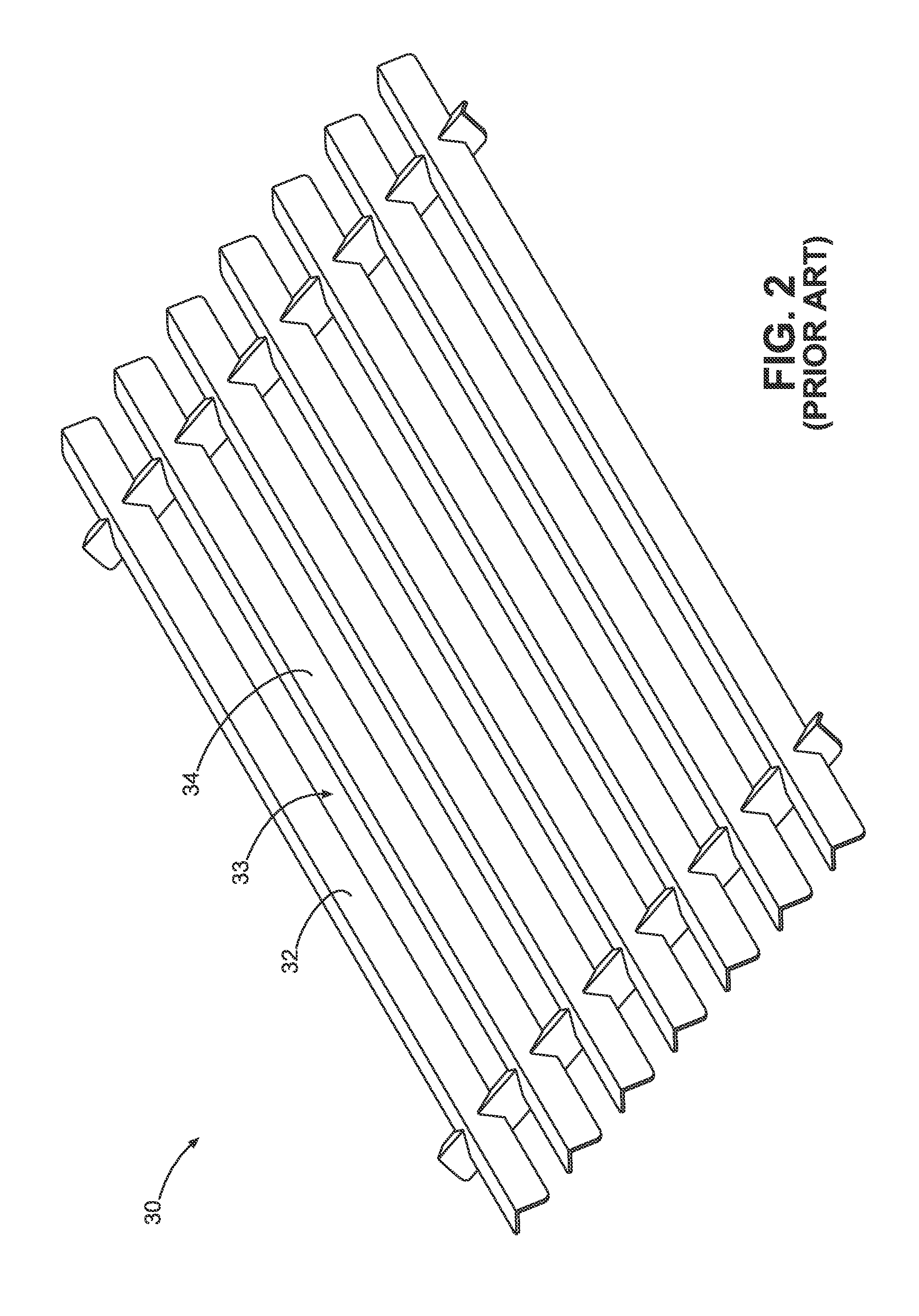
[0028]In the past, cooking grates of the substantially open type have made of stamped sheet metal in the form of inverted V-shaped elements with spaces in between. In these open-grate configurations, the spaces between the elements are of a similar magnitude as the width of the elements. An example of this is shown in FIG. 2, which is an isometric view of a prior art cooking grate 30, with elements 32 and 34 being adjacent elements and a s...


PUM


Abstract

Cooking grates and grills incorporating such cooking grates are provided. A representative cooking grate includes: a plurality of elongate elements of heat resistant material, the elements being V-shaped in transverse cross-section, each of the elements having a first lower edge, a second lower edge and a vertex, the first lower edge and the second lower edge being spaced from each other with the vertex being located therebetween, the vertex being operative as a cooking surface to support food during cooking on the cooking grate; corresponding adjacent lower edges of adjacent ones of the elements being oriented to define gaps therebetween such that a first of the gaps, defined by a first lower edge of a first element and a second lower edge of a second element, exhibits a width of between approximately 5% and approximately 18% of a distance between the first lower edge and the second lower edge of the first element.

Description

CROSS REFERENCE TO RELATED APPLICATION[0001]This utility application claims the benefit of and priority to U.S. provisional application entitled, “Flame Arresting and Heat Radiating Cooking Grate,” having Ser. No. 61 / 061,018, filed Jun. 12, 2008, which is entirely incorporated herein by reference.BACKGROUND[0002]1. Technical Field[0003]This disclosure relates to cooking grills.[0004]2. Description of the Related Art[0005]Outdoor cooking grills are popular for many reasons including enhanced food flavor and enjoyment of the outdoor cooking process. Gas-fired cooking grills are popular for home use and differ from traditional barbecue grills in that they rely upon a gas flame for heat energy, as opposed to the combustion of charcoal briquettes or the like. Conventional burner gas grills frequently utilize generally tubular burners having multiple combustion ports or orifices. In the past, the grills often employed an inert material, such as so-called “lava rocks” or ceramic tiles, to ...

Claims


Application Information

Patent Timeline
Patent Type & Authority Applications(United States)
IPC IPC(8): A47J37/07F23H13/00
CPCA47J37/067A47J37/0704A47J37/0694
Inventor AHMED, MALLIK R.
Owner CHAR BROIL
Why Eureka
Try Eureka