
Wet processing system and wet processing method

a technology of wet processing and wet processing method, which is applied in the field of wet processing system, can solve problems such as the degradation of the uniformity of the conductive pattern

Inactive Publication Date: 2009-12-24
ZHEN DING TECH CO LTD
View PDF10 Cites 9 Cited by
  • Summary
  • Abstract
  • Description
  • Claims
  • Application Information

AI Technical Summary

Benefits of technology

[0002]The present disclosure relates to a wet processing system, and particularly, to a wet processing system with a substrate positioning device, and a related wet processing method.

Problems solved by technology

This will cause degradation of uniformity of the conductive pattern, i.e. short circuit.

Method used


Image

  • Wet processing system and wet processing method
  • Wet processing system and wet processing method
  • Wet processing system and wet processing method

Examples


Embodiment Construction

[0015]An exemplary embodiment will now be described in detail below with reference to the drawings.

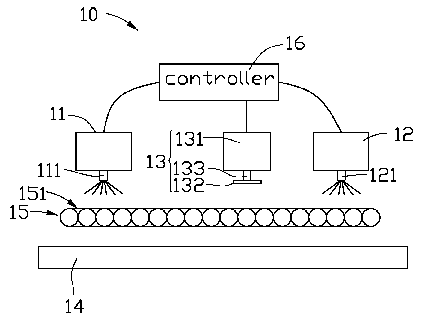
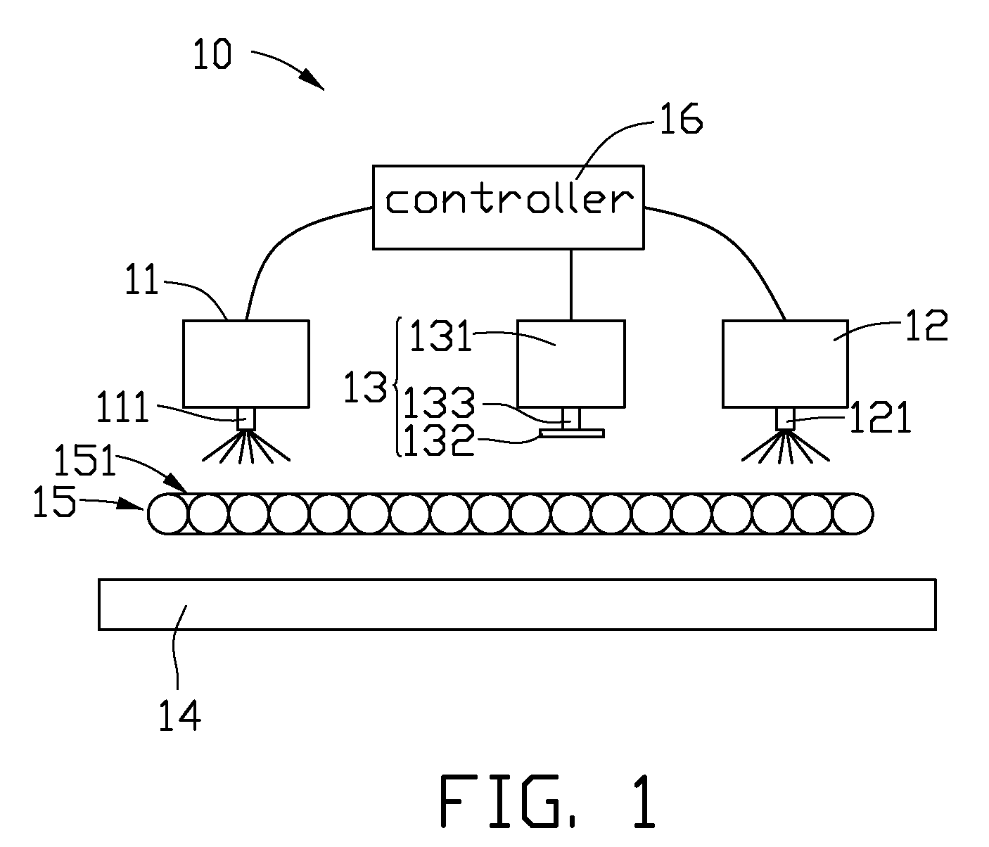
[0016]Referring to FIG. 1, a wet processing system 10 can be used in developing, etching, cleaning, and any other wet processes, in which a workpiece is processed with a corresponding liquid, such as developing agent, etchant, cleaning fluid. In the present embodiment, the system 10 is an etching system.

[0017]The system 10 includes a first liquid spraying device 11, a second liquid spraying device 12, a substrate positioning device 13, a liquid collection container 14, and a conveyor 15. The substrate positioning device 13 is installed between the first and second liquid spraying devices 11, 12. The conveyor 15 is configured for transporting a workpiece (e.g. a substrate) through the first liquid spraying device 11, the substrate positioning device 13 and the second liquid spraying device 12.

[0018]The first liquid spraying device 11 faces the conveyor 15, and is configured for spraying...


PUM

PropertyMeasurementUnit
Structureaaaaaaaaaa

Abstract

An exemplary system for processing a workpiece comprises a conveyor, a first liquid spraying device, a second liquid spraying device, and a substrate positioning device. The conveyor is configured for conveying the workpiece along a conveying direction. The first and second liquid spraying devices for spraying liquid onto the workpiece transported on the conveyor face the conveyor and are arranged along the conveying direction. The substrate positioning device for reorienting the workpiece on the conveyor is installed between the first and second liquid spraying devices and faces the conveyor.

Description

BACKGROUND[0001]1. Technical Field[0002]The present disclosure relates to a wet processing system, and particularly, to a wet processing system with a substrate positioning device, and a related wet processing method.[0003]2. Description of Related Art[0004]At present, as the electronic appliances are becoming smaller in size and diversified in function, printed circuit boards (PCBs) widely used as a key component in such electronic appliances are required to have higher circuit density and reliability, for mounting more various electronic components such as resistor, capacitor, and integrated circuits thereon. To enhance circuit density, a photoresist layer having elongated patterns in various directions is employed, for manufacturing a conductive pattern distributed in various directions to increase a space utility rate of the printed circuit boards and decrease a volume of the printed circuit boards.[0005]Usually, a chemical etching process is used for etching the higher density ...

Claims


Application Information

Patent Timeline
IPC IPC(8): B44C1/22C23F1/08
CPCH05K3/0085H05K3/068H05K2203/0195H05K2203/166H05K2203/082H05K2203/1476H05K2203/1509H05K2203/075
Inventor YANG, CHIH-KANGLEE, WEN-CHIN
Owner ZHEN DING TECH CO LTD
Learn More