Monolithic structurally complex heat sink designs

a heat sink and monolithic technology, applied in the field of heat sinks, can solve the problems of inability to make such complex structures, need more complex structures to improve the performance of heat sinks, and traditional methods of manufacturing heat sinks are not suited to making such complex structures

Inactive Publication Date: 2009-12-31
ALCATEL-LUCENT USA INC
View PDF19 Cites 92 Cited by
  • Summary
  • Abstract
  • Description
  • Claims
  • Application Information

AI Technical Summary

Problems solved by technology

But more complex structures are needed to improve the performance of heat sinks.
Traditional methods of manufacturing heat sinks are not suited to making such complex structures.

Method used


Image

  • Monolithic structurally complex heat sink designs
  • Monolithic structurally complex heat sink designs
  • Monolithic structurally complex heat sink designs

Examples


Embodiment Construction

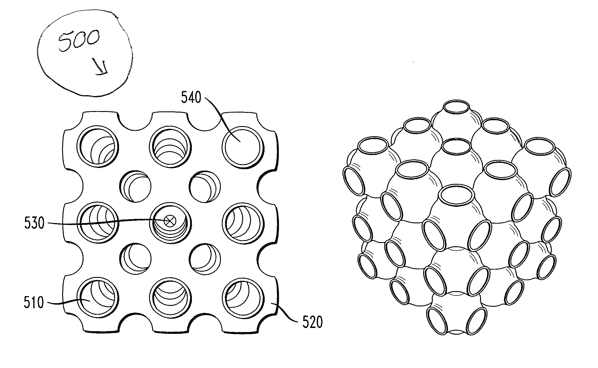
[0016]Embodiments described herein reflect the recognition that three dimensional (3-D) rendering and investment casting may be employed to manufacture monolithic heat sinks with structural complexity unattainable by prior art methods. Such complexity in a monolithic heat sink design provides a means to form heat sinks with novel structural features to improve the performance of such heat sinks over prior art heat sinks. The described embodiments make structural elements available to heat sink designers hitherto unattainable. The availability of these elements provides the designer with the ability to take greater advantage of flow mechanics and heat dissipation physics than with “simple” heat sinks, defined below. Embodiments are described herein that result in a significant improvement of heat transfer characteristics of a structurally complex heat sink relative to simple heat sinks.

[0017]The present discussion introduces the concept of using 3-D printing of a sacrificial pattern ...


PUM

PropertyMeasurementUnit
aspect ratioaaaaaaaaaa
areaaaaaaaaaaa
widthaaaaaaaaaa

Abstract

A heat sink includes a base and a heat exchange element monolithically connected to the base. The heat exchange element has a surface that at least partially bounds first and second paths through the heat exchange element. The surface forms an upper boundary of the first and second paths and includes an opening therethrough connecting the first and second paths.

Description

CROSS-REFERENCE TO RELATED APPLICATIONS[0001]The present application is related to U.S. patent application Ser. No. ______ to Hernon, et al., entitled “Active Heat Sink Designs”, and which is commonly assigned with the present application, and U.S. patent application Ser. No. ______ to Hernon, et al., entitled “Flow Diverters to Enhance Heat Sink Performance,” both of which are hereby incorporated by reference as if reproduced herein in their entirety.TECHNICAL FIELD OF THE INVENTION[0002]The present invention is directed, in general, to heat sinks.BACKGROUND OF THE INVENTION[0003]Heat sinks are commonly used to increase the convective surface area of an electronic device to decrease the thermal resistance between the device and a cooling medium, e.g., air. Various manufacturing methods are used, including extrusion, machining and die-casting. These methods are suitable for relatively simple heat sinks. But more complex structures are needed to improve the performance of heat sinks....

Claims


Application Information

Patent Timeline
Patent Type & Authority Applications(United States)
IPC IPC(8): F28F7/00
CPCF28F13/003H01L23/367H01L23/467B22D25/02Y10T29/4935F28F2255/00H01L2924/0002H05K7/20009H01L2924/00B33Y80/00H01L23/3672H01L23/34H01L23/36H05K7/20
Inventor HERNON, DOMHNAILLHODES, MARCLYONS, ALANO'LOUGHLIN, ALANKRISHNAN, SHANKAR
Owner ALCATEL-LUCENT USA INC
Why Eureka
Try Eureka