Method and device for travel time-based location identification with the aid of a triggered or self-triggering reference signal

Inactive Publication Date: 2009-12-31
SIEMENS AG
View PDF9 Cites 13 Cited by
  • Summary
  • Abstract
  • Description
  • Claims
  • Application Information

AI Technical Summary

Benefits of technology

[0027]Further advantageous embodiments are set forth in the dependent claims.
[0028]According to one advantageous embodiment, the signal from the object X and signal from the reference station R are transmitted simultaneously in two different channels. The use of two different channels for object X and reference station R enables the fully synchronous transmission of signals from both stations. In this way the measurement rate, i.e. the number of measurements per second, and an achievable precision can advantageously be improved. The transmission offset ΔtXR between the transmission of the signal from the object X and the transmission of the signal from the reference station R is zero and consequently does not need to be taken into account any further.
[0029]According to a further advantageous embodiment, the object X and the reference station R are prompted by a station Bi to transmit their signals simultaneously by means of a common trigger line. Both the reference station R and the object X are prompted to transmit their signals simultaneously by way of a common trigger line which can be wired or wireless.
[0030]According to a further advantageous embodiment, the reference station R transmits in a first channel, or in a second channel if the reference station R has detected that the object X is transmitting in a first channel, with a time offset ΔtXR being applicable between the transmission of the signal by the object X and the transmission of the signal by the reference station R. R transmits only after X has transmitted. Particularly advantageously, no synchronization must be produced between the two signals. Use of a common channel or two different channels is possible. According to this embodiment the reference station R is passive until it has detected a signal from object X. Then the signal of the reference

Problems solved by technology

A clock offset leads to positio

Method used


Image

  • Method and device for travel time-based location identification with the aid of a triggered or self-triggering reference signal
  • Method and device for travel time-based location identification with the aid of a triggered or self-triggering reference signal
  • Method and device for travel time-based location identification with the aid of a triggered or self-triggering reference signal

Examples


Embodiment Construction

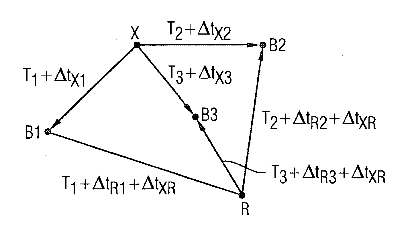
[0041]FIG. 1 shows an object X and three fixed stations B1, B2 and B3. The object X transmits a signal which reaches the fixed stations B1, B2 and B3 after the travel times Δt1, Δt2 and Δt3. If all the stations are in the same time axis, i.e. all the stations have the same initial time offset T0, correct time differences are determined which, with the aid of a triangulation, can lead to the identifying of the location of X (formula 1):

Δt12=(T0+Δt2)−(T0+Δt1)=Δt2−Δt1

Δt23=(T0+Δt3)−(T0+Δt2)=Δt3−Δt2

Δt31=(T0+Δt1)−(T0+Δt3)=Δt1−Δt3

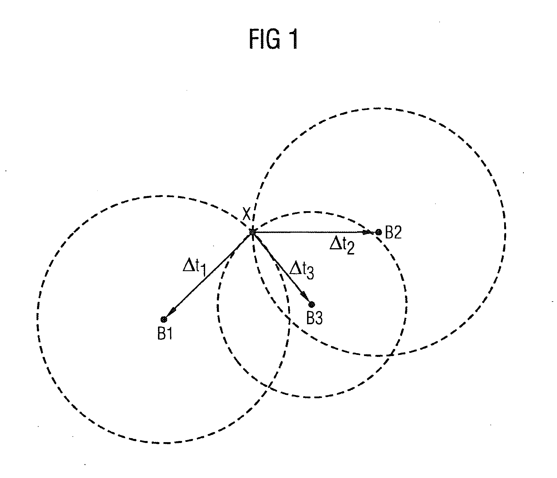
[0042]FIG. 2 shows that with unknown different time offsets T1, T2 and T3 are no longer removed from the time differences (formula 2):

Δt12=(T2+Δt2)−(T1+Δt1)

Δt23=(T3+Δt3)−(T2+Δt2)

Δt31=(T1+Δt1)−(T3+Δt3)

[0043]Determining an object's position can only be carried out with inaccuracies. A measured position X′ differs from the actual position X:

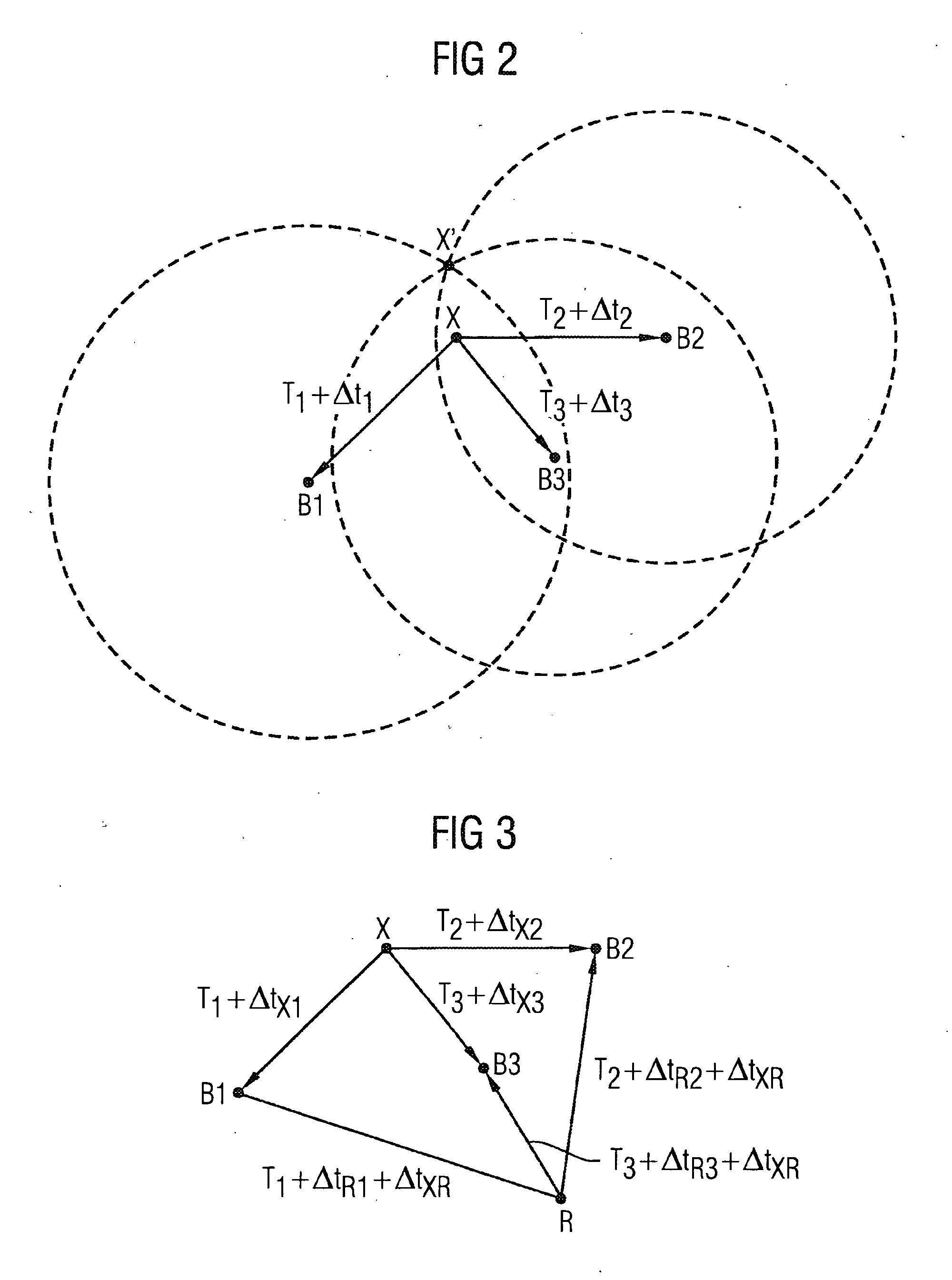
[0044]FIG. 3 shows an exemplary embodiment of an arrangement according to the invention. Said arrangement corresponds to that de...


PUM


Abstract

A method for the detection of an object by the TDOA principle is provided. The object transmits a signal, which is received by a plurality of stations having known positions. The stations' clocks can have different unknown time delays in relation to each other. An additional stationary reference station having a known position relative to the stations and transmitting a signal that is received by the stations is provided. An unknown transmission delay can be generated between the emission of the signal from the object and the emission of the signal from the reference station. For each station the difference in travel time between receipt of the signal from the object and the signal from the reference station and the difference of the travel time differences between the stations are determined. Mathematical algorithms for determining the location are performed.

Description

CROSS REFERENCE TO RELATED APPLICATIONS[0001]This application is the US National Stage of International Application No. PCT / EP2007 / 058747, filed Aug. 22, 2007 and claims the benefit thereof. The International Application claims the benefits of German application No. 10 2006 040 497.1 DE filed Aug. 30, 2006, both of the applications are incorporated by reference herein in their entirety.FIELD OF INVENTION[0002]The present invention relates to a method according to the preamble of the main claim and a device according to the preamble of the coordinated claim.BACKGROUND OF INVENTION[0003]A large number of location identification / positioning methods and systems use what is known as the TDOA principle, where TDOA stands for “Time Difference of Arrival”. In this way it becomes possible to locate objects, in particular terminal devices. Toward that end an object whose location is to be identified transmits a signal which is received by a plurality of fixed stations. The time difference bet...

Claims


Application Information

Patent Timeline
IPC IPC(8): G01S5/06
CPCG01S5/06G01S5/021
Inventor SCHWARZER, STEFANSEISENBERGER, CLAUS
Owner SIEMENS AG
Why Eureka
Try Eureka