Multi-Frequency Band Receiver

a receiver and multi-frequency band technology, applied in the direction of direction finders, modulated carrier systems, transmission, etc., can solve the problems of large space occupation, high cost, and insufficient broadband for several frequency bands of single input stages, so as to reduce the number of oscillators, reduce current consumption, and reduce the effect of cos

Inactive Publication Date: 2011-06-02
FRAUNHOFER GESELLSCHAFT ZUR FOERDERUNG DER ANGEWANDTEN FORSCHUNG EV
View PDF26 Cites 23 Cited by
  • Summary
  • Abstract
  • Description
  • Claims
  • Application Information

AI Technical Summary

Benefits of technology

[0025]On the other hand, the current consumption is also reduced.
[0026]In addition, the requirements placed upon the components—as compared to a receiver having only one processing path for all of the frequency bands—may be reduced, since components having smaller bandwidths may be used for the individual paths, which also results in a cost reduction.
[0027]Moreover, by utilizing the same local oscillator signal in several paths, the number of oscillators that may be used, or the complexity of the oscillator stage, may be reduced, whereby even further components may be saved.
[0028]In some embodiments, for example mirror-frequency suppression will be omitted because of the matching of the local oscillator signal of the oscillator stage with the frequency bands processed in a shared path, since in this case, a frequency band will represent the mirror frequency of another frequency band. As a result, the complexity and, thus, the number of components that may be used may be reduced.
[0029]In some further embodiments, due to matching of the signals of the oscillator stage with the frequency bands to be processed, the receiver may make do with only one oscillator stage and with only one baseband stage, which leads to a reduction in the components that may be used, and therefore increases the efficiency with regard to space, cost and power consumption.
[0030]In some embodiments in accordance with the invention, at least two of the frequency bands processed in a shared path are modulated such that during processing of the signals, a highpass filter may suppress interference such as 1 / f noise or a DC (direct voltage) offset.

Problems solved by technology

Consequently, a large number of components and, therefore, a large amount of space may be used.
Likewise, the current consumption of the input stages of the different frequency bands add up considerably, which is often critical, for example, for mobile satellite navigation receivers, but also in many other fields.
A single input stage that is sufficiently broadband for several frequency bands, or a sufficiently broadband front end, is very costly and may consume a large amount of current due to the high bandwidth.
Processing of several frequency bands in only one broadband input stage not only strongly increases the current consumption, but the requirements placed upon the various components are also very high, since the components are designed for a broad frequency range.
Other approaches utilize an input architecture, or front-end architecture, that may be switched to other frequency bands as desired—however, this does not provide any advantage for ionosphere correction, for example, since for this purpose, at least two frequency bands may be available at the same time.
Thus, for any applications requiring real-time information from several frequency bands, a switchable input architecture processing the various frequency bands one after the other is not useful.

Method used


Image

  • Multi-Frequency Band Receiver
  • Multi-Frequency Band Receiver
  • Multi-Frequency Band Receiver

Examples


Embodiment Construction

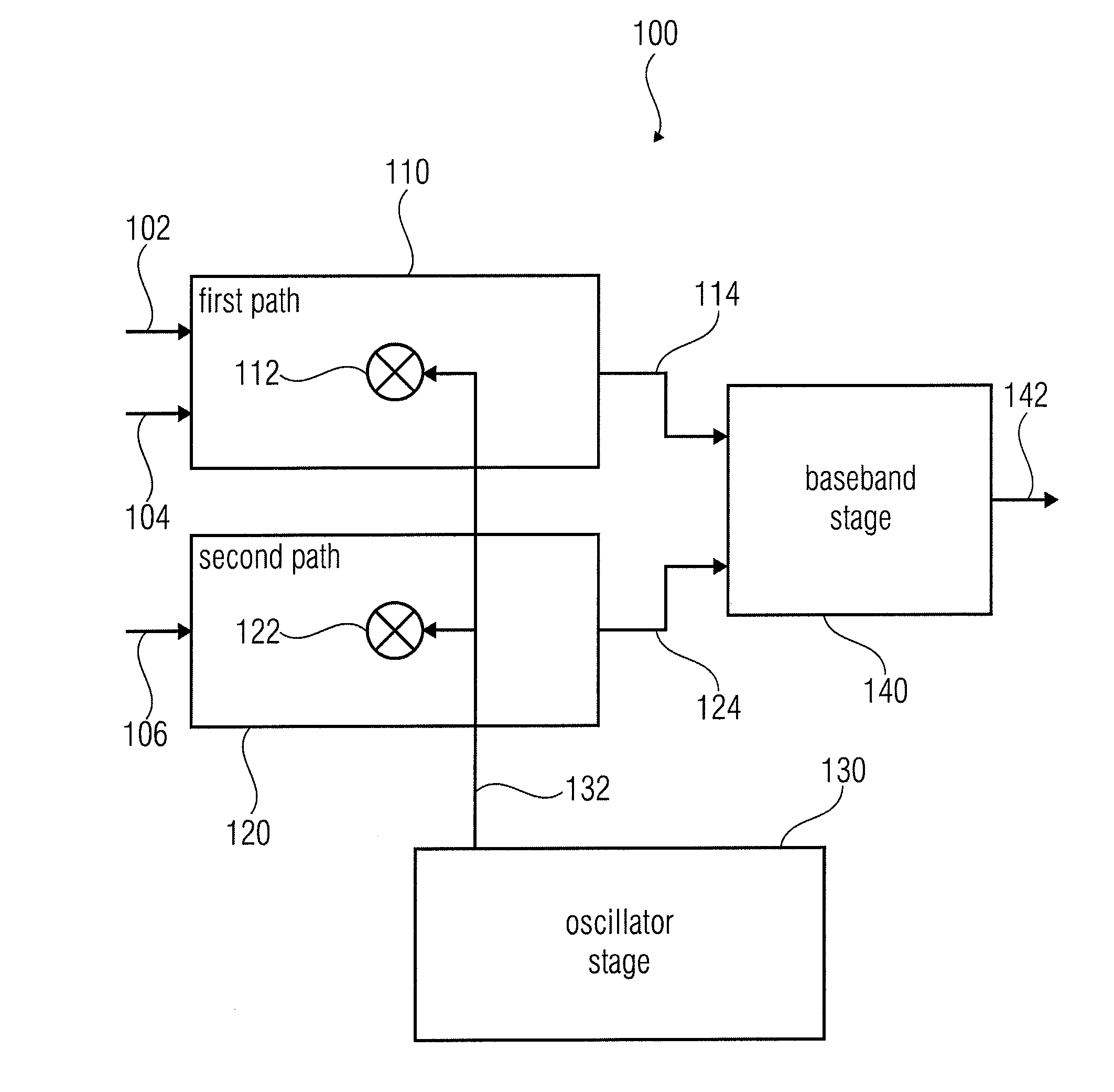
[0044]FIG. 1 shows a block diagram of a multi-frequency band receiver 100 in accordance with an embodiment of the invention. The receiver 100 comprises a first path 110 for processing a first frequency band 102 and a second frequency band 104, and a second path 120 for processing a third frequency band 106. The first frequency band 102 and the second frequency band 104 have a smaller distance than the first frequency band 102 and the third frequency band 106, and a smaller distance than the second frequency band 104 and the third frequency band 106. In addition, the receiver comprises an oscillator stage 130 for providing a local oscillator signal 132. The frequency of the local oscillator signal 132 is between the center frequency of the first frequency band 102 and the center frequency of the second frequency band 104. In addition, the first path 110 and the second path 120 each have one mixer 112, 122, it being possible for both mixers 112, 122 to be supplied with the same local ...


PUM


Abstract

A multi-frequency band receiver has a first path configured to process first and second frequency bands, and a second path configured to process a third frequency band, the first and second frequency bands having a smaller distance than the first and third frequency bands, and having a smaller distance than the second and third frequency bands. In addition, the multi-frequency band receiver has an oscillator stage for providing a local oscillator signal having a frequency that is between the center frequencies of the first and second frequency bands, the first path having a mixer that may be supplied with the local oscillator signal, and the second path having a mixer that may also be supplied with the local oscillator signal. In addition, the multi-frequency band receiver has a baseband stage for processing output signals of the first and second paths so as to obtain a receive signal.

Description

CROSS-REFERENCE TO RELATED APPLICATIONS[0001]This application is a Continuation of PCT Patent Application No. PCT / EP2009 / 003874 filed 29 May 2009, and claims priority to German Patent Application Serial No. 102008026698.1-35 filed 4 Jun. 2008, which are incorporated herein in their entirety by this reference thereto.BACKGROUND OF THE INVENTION[0002]Embodiments in accordance with the invention relate to wireless data communication, and in particular to a multi-frequency band receiver and to a method of receiving signals using a multi-frequency band receiver.[0003]Feasible input architectures, or front-end architectures (front end: input-side component), for Global Navigation Satellite System receivers (GNSS receivers) are designed to only receive one frequency band in each case. However, for high-precision GNSS receivers, it is precisely the reception of several frequency bands that is of vital importance, since it is only in this manner that inaccuracies due to ionospheric effects, ...

Claims


Application Information

Patent Timeline
Patent Type & Authority Applications(United States)
IPC IPC(8): H04L27/00H04B1/69
CPCG01S19/13G01S19/36G01S19/33G01S19/32
Inventor RUEGAMER, ALEXANDERURQUIJO TARDIO, SANTIAGO
Owner FRAUNHOFER GESELLSCHAFT ZUR FOERDERUNG DER ANGEWANDTEN FORSCHUNG EV
Why Eureka
Try Eureka