Check patentability & draft patents in minutes with Patsnap Eureka AI!

Method, device, and system for guaranteed minimum processor power state dwell time

a technology of minimum processor power state and dwell time, applied in the direction of liquid/fluent solid measurement, sustainable buildings, instruments, etc., can solve the problems of power inefficiency of certain processors, significant and power hungry requirements,

Active Publication Date: 2009-12-31
INTEL CORP
View PDF8 Cites 26 Cited by
  • Summary
  • Abstract
  • Description
  • Claims
  • Application Information

AI Technical Summary

Problems solved by technology

Other power states have significant and power hungry requirements for performing the entry and exit processes.
With a particular workload, certain processors can become power inefficient if they are continually forced to enter and exit a power state that has highly power inefficient entry and exit processes.

Method used


Image

  • Method, device, and system for guaranteed minimum processor power state dwell time
  • Method, device, and system for guaranteed minimum processor power state dwell time
  • Method, device, and system for guaranteed minimum processor power state dwell time

Examples


Embodiment Construction

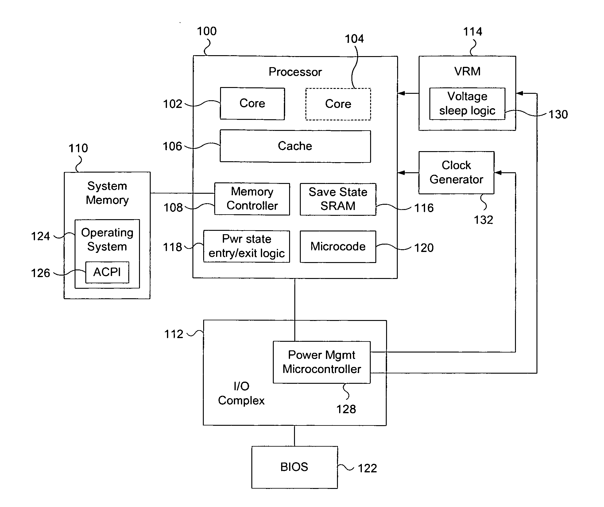
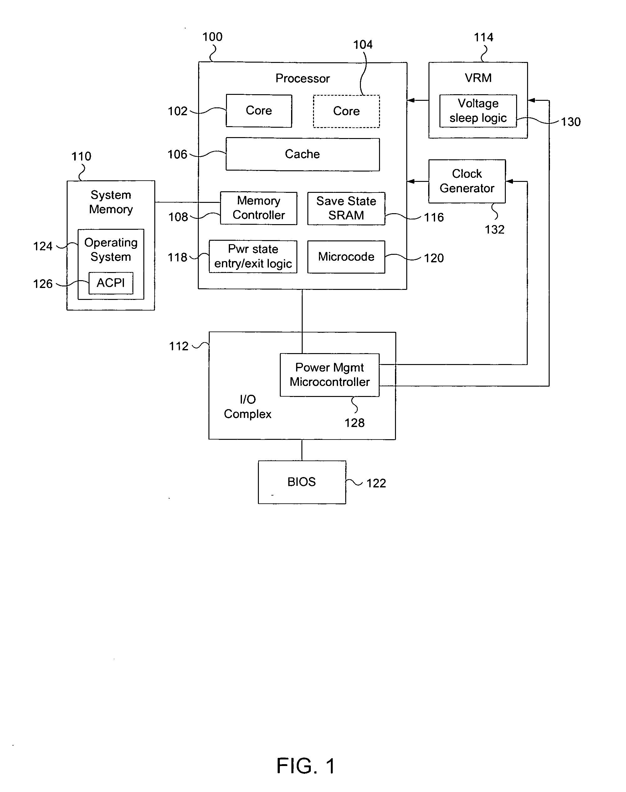
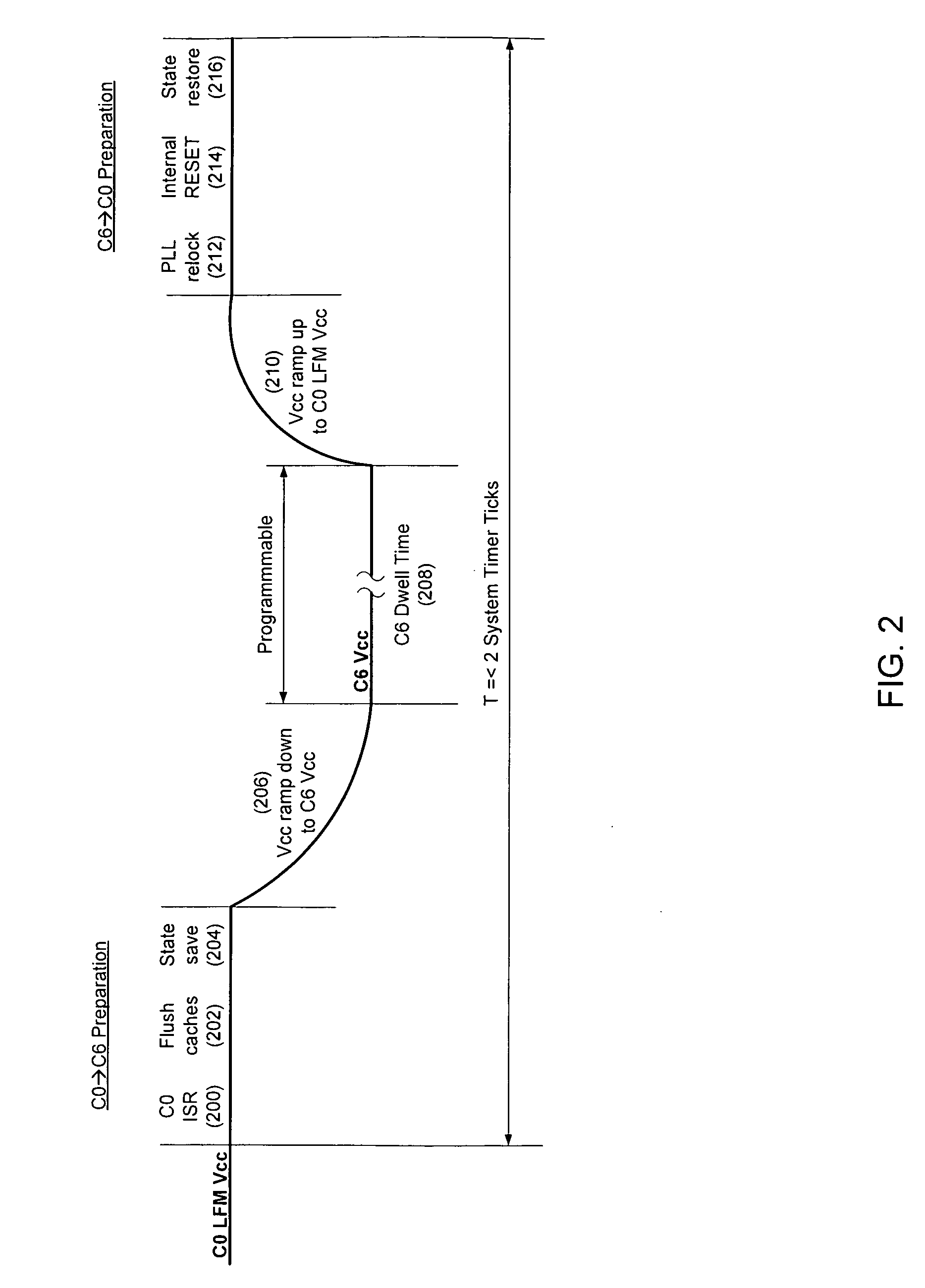
[0006]Embodiments of a method, device, and system for enforcing a minimum dwell time a processor must remain in a particular power state are disclosed. The processor can enter a power state that has an associated minimum dwell time. Once the processor is in the power state with the minimum dwell time, the processor must remain in that state until the minimum dwell time has passed. Thus, any interrupts (i.e. break events) that would otherwise cause the processor to immediately exit the power state will not be honored until the minimum dwell time has passed. Rather, the break event(s) will be held in waiting and then allowed to proceed to cause the processor to exit the power state when the processor has been at least been in the power state for the duration of the minimum dwell time.

[0007]Reference in the following description and claims to “one embodiment” or “an embodiment” of the disclosed techniques means that a particular feature, structure, or characteristic described in connec...


PUM


Abstract

A method, device, and system are disclosed. In one embodiment the method includes causing a processor to enter into a first power state. Then an interrupt is received that signals the processor to leave the first power state. The method continues by causing the processor to remain in the first power state if the interrupt was received less than a minimum dwell time after the processor entered the first power state.

Description

FIELD OF THE INVENTION[0001]The invention relates to guaranteeing a dwell time in a processor power state.BACKGROUND OF THE INVENTION[0002]Many modern processors have multiple power states, which can be utilized to balance the needed performance of the processor against the power the processor consumes. Some power states are relatively efficient to enter into and exit from. Other power states have significant and power hungry requirements for performing the entry and exit processes. With a particular workload, certain processors can become power inefficient if they are continually forced to enter and exit a power state that has highly power inefficient entry and exit processes.BRIEF DESCRIPTION OF THE DRAWINGS[0003]The present invention is illustrated by way of example and is not limited by the drawings, in which like references indicate similar elements, and in which:[0004]FIG. 1 describes an embodiment of a device and computer system capable of providing a minimum dwell time in a ...

Claims


Application Information

Patent Timeline
IPC IPC(8): G06F13/24G06F1/26
CPCG06F1/3203Y02B60/1239G06F1/3243Y02D10/00
Inventor FLETCHER, TERRY
Owner INTEL CORP
Features
  • R&D
  • Intellectual Property
  • Life Sciences
  • Materials
  • Tech Scout
  • Unparalleled Data Quality
  • Higher Quality Content
  • 60% Fewer Hallucinations
Learn More