Patient interface systems

a patient interface and patient technology, applied in the field of patient interface systems, can solve the problems of patients who may snore, may not be suitable for treatment using closed pap methods, may experience mild sleep apnea, may not gain a significant benefit from the use of closed pap treatment,

Active Publication Date: 2010-01-07
RESMED LTD
View PDF102 Cites 900 Cited by
  • Summary
  • Abstract
  • Description
  • Claims
  • Application Information

AI Technical Summary

Benefits of technology

[0018]According to yet another sample embodiment, a patient interface system for delivering a flow of breathable gas to a patient comprises a patient interface support structure configured to be connected to a hose that delivers the flow of breathable gas; a pair of nasal pillows supported by the patient interface support structure, wherein each nasal pillow is c

Problems solved by technology

Mild or moderate cases of SDB may not be suitable for treatment using closed PAP methods.
For example, patients who experience mild sleep apnea, or who may snore, may not gain a significant benefit from the use of closed PAP treatment.
In addition, such patients may tend to resist treatment as closed PAP treatment methods generally

Method used


Image

  • Patient interface systems
  • Patient interface systems
  • Patient interface systems

Examples


first embodiment

1.1.1 Mechanical Fixation First Embodiment

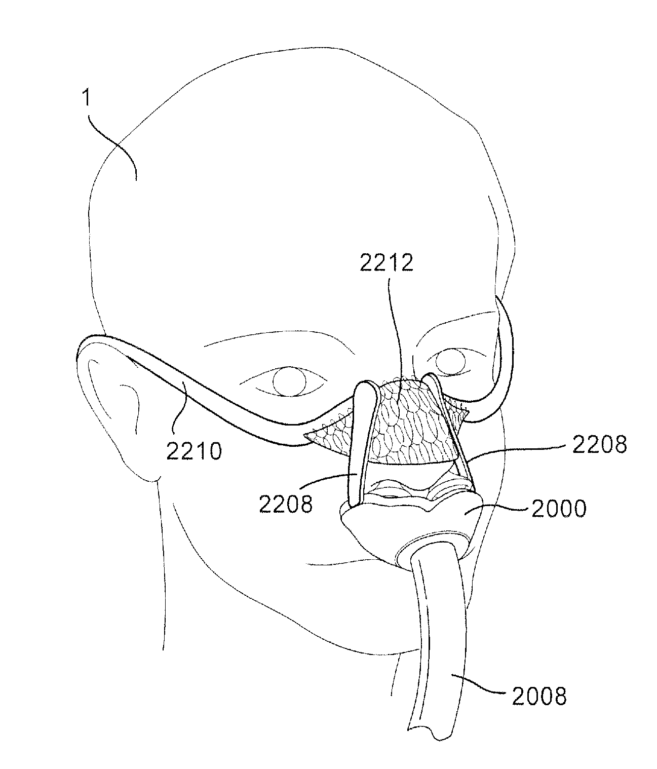
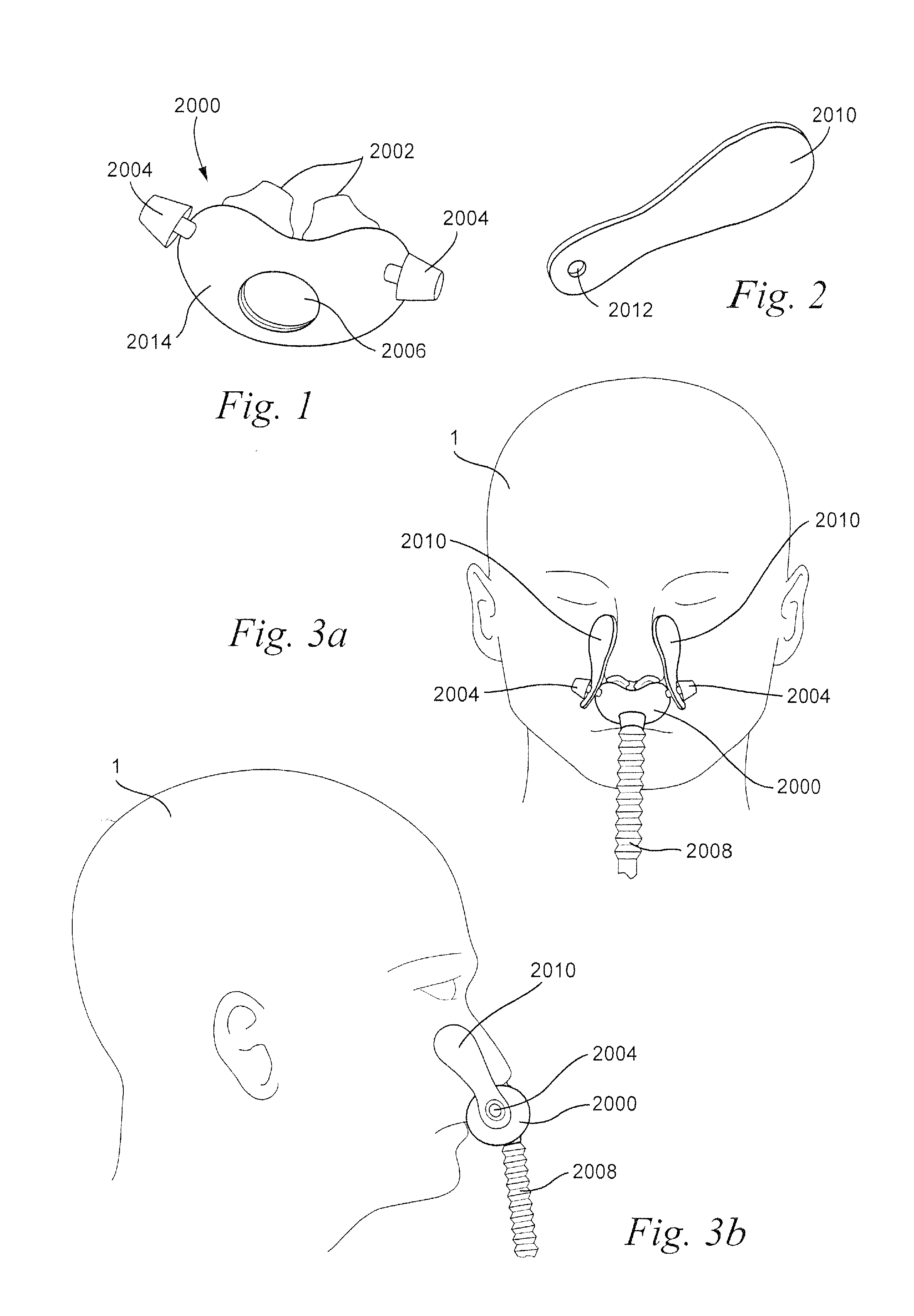
[0124]Referring to FIGS. 1-3b, a patient interface structure may comprise a patient interface structure, e.g. a cushion, 2000 comprising nasal pillows, puffs, or prongs 2002. The patient interface structure 2000 may also comprise tabs, or studs, 2004 at opposite ends of a base portion 2014. The patient interface structure 2000 may further include an aperture 2006 configured to allow for connection of a tube, hose, or conduit 2008. The tube 2008 may be, for example, a retractable tube, such as disclosed in U.S. Patent Application Publication 2009 / 0078259 A1, the entire contents of which are incorporated herein by reference.

[0125]The studs 2004 are each configured to be connected to a patient adhesive strip 2010 that includes a hole 2012 at a first end. The studs 2004 are inserted through the holes 2012 of the patient adhesive strip 2010 to secure the patient adhesive strips 2010 to the patient interface structure. The top portion of stud 2004...

second embodiment

1.1.2 Mechanical Fixation Second Embodiment

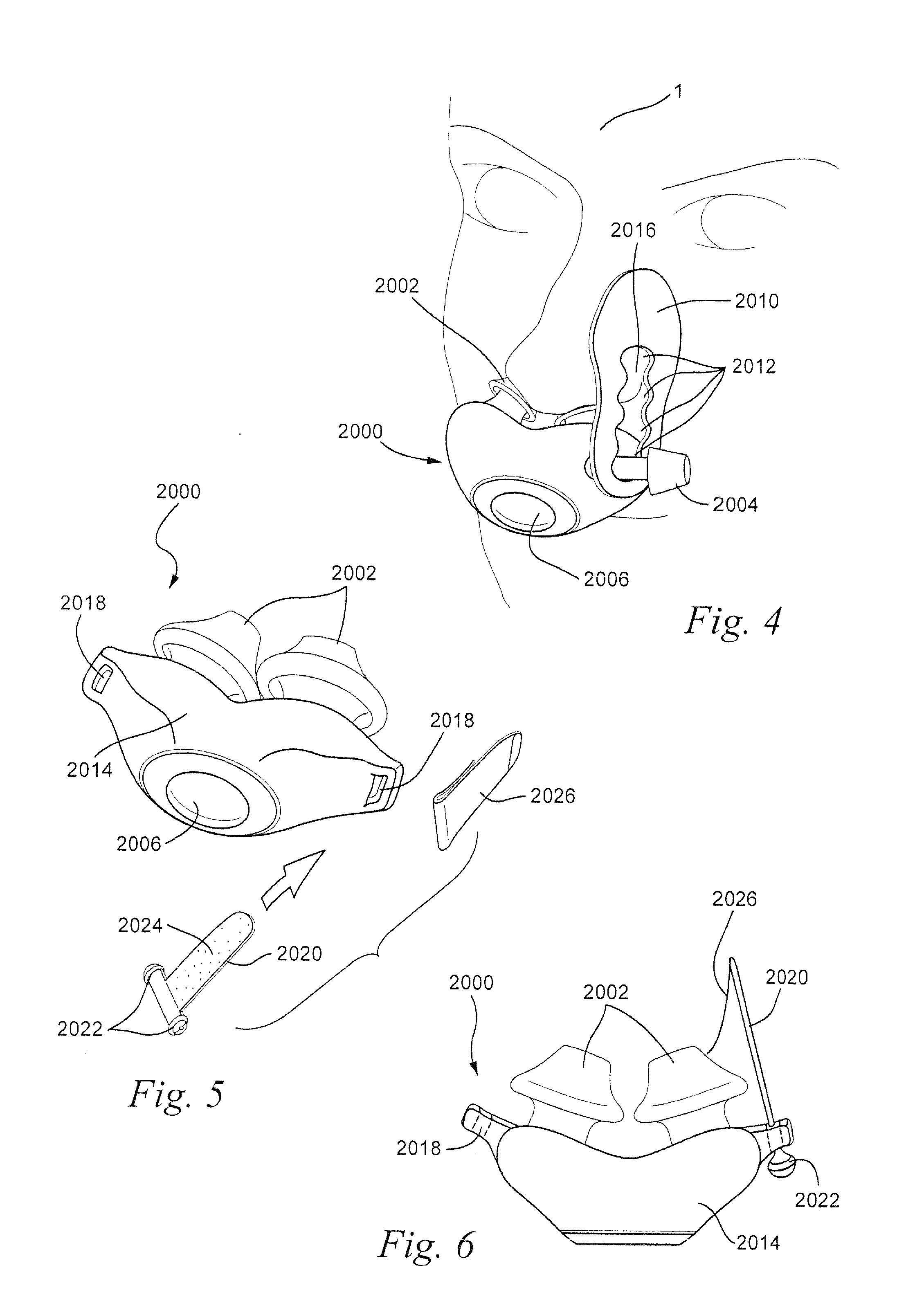
[0129]Referring to FIG. 4, the patient adhesive strips 2010 (only one shown) may include a plurality of holes or spacings 2012 that are each configured to accept the tab or stud 2004 of the patient interface structure 2000. As shown in FIG. 4, the plurality of holes 2012 are joined by a channel 2016 formed in the patient adhesive strip 2010 that permits the stud 2004 to be disengaged from one hole and engaged with another hole without completely disengaging the patient adhesive strip 2010 from the stud 2004. The stud 2004 may be disengaged from one hole 2012 and engaged with another hole 2012 to permit adjustment of the position of the patient adhesive strip 2010 without completely disengaging the adhesive strip 2010 from the patient interface structure 2000. It should be appreciated that the holes 2012 of the patient adhesive strip 2010 may be formed separately, i.e. without a channel, so that adjustment of the position of the patient adhe...

third embodiment

1.1.3 Mechanical Fixation Third Embodiment

[0130]Referring to FIGS. 5-7, the patient interface system may comprise a patient interface structure 2000 provided with loops 2018 on opposite sides of the patient interface structure 2000. Patient adhesive strips 2020 (only one shown) may be inserted through the loops 2018 and locked in place on the patient interface structure 2000 by locking tabs 2022. The locking tabs 2022 may be rigid or semi-rigid (for example, silicone, polycarbonate, polypropylene, thermoplastic elastomers (TPE), etc.) and are provided to the adjoining ends of the patient adhesive strips 2020. The adhesive 2024 of the patient adhesive strips 2020 may be covered by, for example, release paper 2026 to allow the patient adhesive strips 2020 to be inserted through the loops 2018 so that the patient adhesive strips 2020 can be pulled through the loops 2018 until the locking tabs 2022 engage with the loops 2018.

[0131]The locking tabs 2022 may be molded onto the patient adh...


PUM


Abstract

A patient interface system for delivering a flow of breathable gas to a patient includes a patient interface structure configured to sealingly engage the patient's nares; a pair of strips configured to be connected to opposite sides of the patient interface structure; and adhesive configured to secure the patient interface structure in sealing engagement with the patient's nares. The adhesive may be provided on the strips, and the strips are configured to be adhered to sides of the patient's nose by the adhesive. Another patient interface system includes a first component including adhesive on a first side and hook or loop fastener material on a second side, wherein the adhesive is configured to adhere the component to the face of the patient; and a patient interface structure configured to sealingly engage the patient's airways. The patient interface structure includes a second component including a corresponding loop or hook fastener material configured to engage the corresponding hook or loop fastener material of the first strip to secure the patient interface structure in sealing engagement with the patient's face. A patient interface system for delivering a flow of breathable gas to a patient includes a patient interface structure including a pair of nasal prongs or pillows configured to sealingly engage the patient's nares; and at least one spring configured to bias the nasal prongs or pillows outwards into engagement with the nares of the patient.

Description

CROSS REFERENCE TO RELATED APPLICATIONS[0001]This application claims priority to U.S. Applications 61 / 058,659, filed Jun. 4, 2008, and 61 / 080,847, filed Jul. 15, 2008, the entire contents of each being incorporated herein by reference.FIELD OF THE INVENTION[0002]The present invention relates to patient interface systems for delivery of a flow of breathable gas to a patient. The present invention also relates to patient interface systems that may include adhesive(s) to support the patient interface in engagement with the patient and / or a patient interface positioning and / or support structure.BACKGROUND OF THE INVENTION[0003]The use of positive airway pressure (PAP) for the treatment of sleep disordered breathing (SDB), such as obstructive sleep apnea (OSA), was disclosed in U.S. Pat. No. 4,944,310. Treatment using PAP, which may be continuous PAP (CPAP), involves the use of a patient interface which is attached to the patient's face for the provision of the flow of breathable gas. PA...

Claims


Application Information

Patent Timeline
IPC IPC(8): A61M16/06
CPCA61M16/0666A61M16/0688A61M16/0683A61M16/0003A61M16/0605A61M16/0627A61M16/0694A61M16/06A61M2202/02A61M2202/0007A61M16/0875A61M16/0825A61M16/0611A61M16/0616A61M16/0633
Inventor KOOIJ, MICHIELHOWARD, SCOTT ALEXANDERFORMICA, JUSTINRUMMERY, GERARD MICHAELFLOWER, RENEE FRANCESBARLOW, ADAMGIBSON, JOEL EDWARDMAZZONE, DAMIEN JULIANDAVIDSON, AARON SAMUELLANG, BERND CHRISTOPHBIENER, ACHIMREID, MICHAEL JOHN
Owner RESMED LTD
Why Eureka
Try Eureka