Breathing assistance apparatus

a technology of nasal devices and breathing chambers, which is applied in the field of nasal cannulae, can solve the problems of nasal devices dislodging from the breathing cavity, conventional cannulas not providing a proper seal around the nares, and deemed uncomfortable by patients, and achieves the effect of low resistan

Inactive Publication Date: 2011-03-15
FISHER & PAYKEL HEALTHCARE LTD
View PDF122 Cites 40 Cited by
  • Summary
  • Abstract
  • Description
  • Claims
  • Application Information

AI Technical Summary

Benefits of technology

[0012]It is an object of the present invention to provide a nasal cannula which goes someway to overcoming the above mentioned disadvantages or which will at least give the public a useful choice.
[0025]said nasal cannula including a low resistance path between said inhalatory conduit and said exhalatory conduit.

Problems solved by technology

Despite their convenience, nasal based devices are deemed uncomfortable in light of securement straps placed across the face and / or around the head and used to secure the device to an individuals breathing cavity.
Moreover, conventional cannulas do not provide a proper seal around the nares to inhibit apnea and to provide a high flow system to stimulate the patient's breathing.
Hence, even with such securement straps, these nasal devices often dislodge from the breathing cavity.
If the air volume falls below this minimum level, then the lungs may collapse, which can be extremely dangerous or even deadly to the individual.
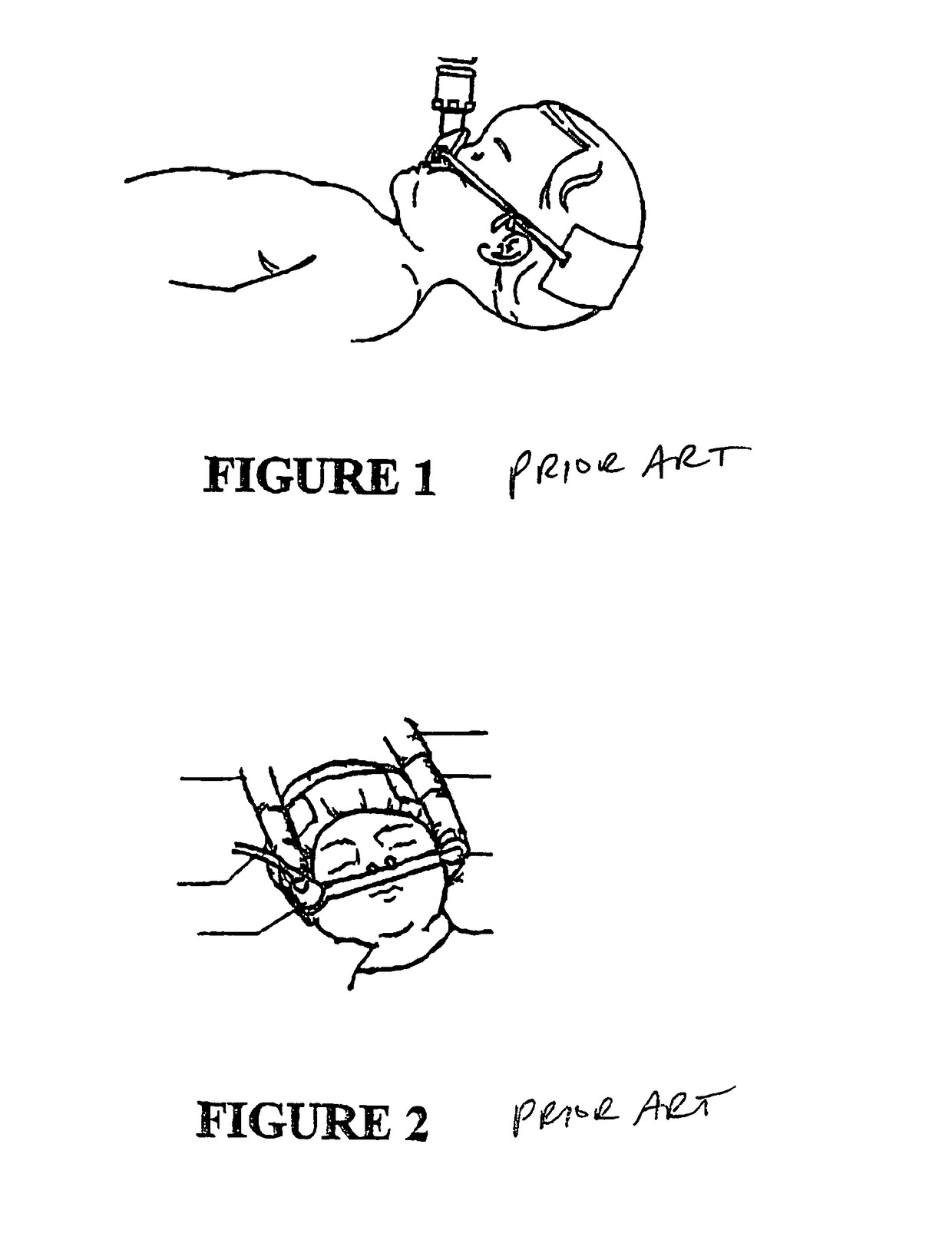
Even more cumbersome, U.S. Pat. No. 5,477,852 discloses a device with a headband for holding and positioning the nasal inserts and associated supply tubes.
However, this method generally puts pressure on an individual's nose and upper lip thereby causing pressure necrosis in the centre of the nose.
The bonnet also fails to adequately keep the nasal prongs in position, particularly with infants who move or roll around in their crib.
In a hospital or care facility setting, it is not uncommon for an attendant to discover that the CPAP device has been disconnected from a patient's nose, which can lead to apnea, desaturations, bradycardia, or hypoxia which is dangerously low oxygen levels in the blood.
Pressure on the patient's cheeks caused by the securement device can make other positions uncomfortable.
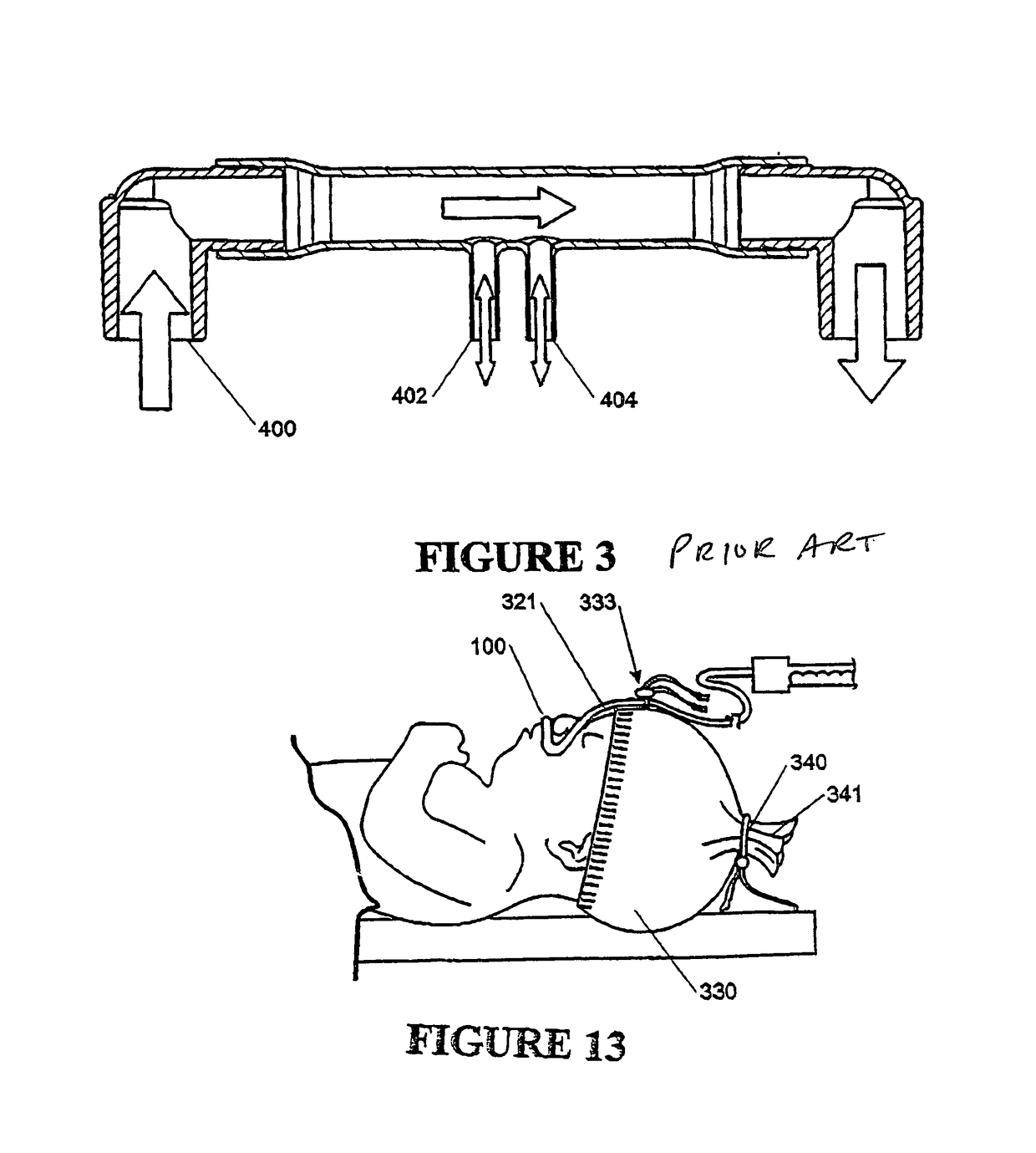
However, while these prior art systems do provide nasal CPAP they suffer from a number of disadvantages including: insufficiently securement to the patients head, potential for unbalanced pressure in each prong, and potential for rebreathing of expired CO2.

Method used


Image

  • Breathing assistance apparatus
  • Breathing assistance apparatus
  • Breathing assistance apparatus

Examples


Embodiment Construction

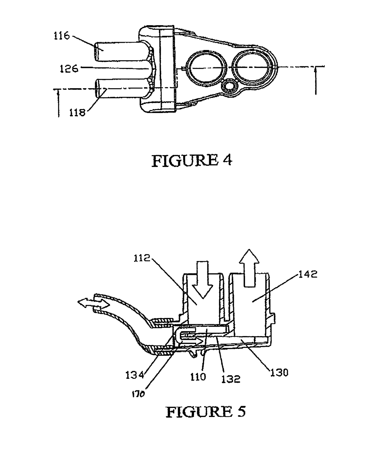
[0042]Referring now to FIG. 11 in which a typical application is depicted. A humidified Continuous Positive Airway Pressure (CRAP) system is shown in which a patient 19 is receiving humidified and pressurised gases through a nasal cannula 100 connected to a inhalatory conduit 21. It should be understood that the present invention, however, is not limited to the delivery of CPAP gases but is also applicable to other types of gases delivery systems. Inhalatory conduit 21 is connected to the outlet 12 of a humidification chamber 10 which contains a volume of water 15. Inspiratory conduit 21 may contain heating means or heater wires 20 which heat the walls of the conduit to ensure a constant humidity profile along the conduit and therefore reduce condensation of humidified gases within the conduit. As the volume of water 15 within humidification chamber 10 is heated, water vapour begins to fill the volume of the chamber above the water's surface and is passed out of the humidification c...


PUM


Abstract

A nasal cannula for delivering respiratory gas to a neonatal infant includes a gas inlet configured to engage a respiratory conduit, a gas outlet configured to engage an expiratory conduit, and a pair of nasal prongs. The gases inlet and the gases outlet are in fluid communication via a low resistance path. Each of the nasal prongs is located substantially equidistant from, and in fluid communication with, the gases inlet, and substantially equidistant from and in fluid communication with, the gases outlet. The nasal prongs are juxtaposed directly in the low resistance path.

Description

FIELD OF INVENTION[0001]This invention relates to Nasal Cannulae particularly though not solely to nasal cannulae for delivering Continuous Positive Airway Pressure (CPAP) to neonates.BACKGROUND[0002]Certain individuals require a respiratory supplement such as air, oxygen, or other gases. Such gases are freely supplied and / or supplied at controlled pressures. Such gases are also supplied through the patient's mouth and / or through the patient's nose. Nasal supply systems provide an advantage in that they are generally more convenient and less intrusive than mouth based or mouth covering devices. Despite their convenience, nasal based devices are deemed uncomfortable in light of securement straps placed across the face and / or around the head and used to secure the device to an individuals breathing cavity. Moreover, conventional cannulas do not provide a proper seal around the nares to inhibit apnea and to provide a high flow system to stimulate the patient's breathing. Hence, even wi...

Claims


Application Information

Patent Timeline
Patent Type & Authority Patents(United States)
IPC IPC(8): A61G10/00A62B18/08A62B18/02A61M16/00A62B9/02A61M16/06A61M16/10A61M16/16A61M16/20
CPCA61M16/06A61M16/0666A61M16/0683A61M16/1095A61M16/0069A61M16/0633A61M16/0066A61M16/16A61M2205/3348A61M2240/00A61M16/208A61M16/161A61M16/0841
Inventor OLSEN, GREGORY JAMESLECKIE, MARTINPRIME, NEIL
Owner FISHER & PAYKEL HEALTHCARE LTD
Why Eureka
Try Eureka