Heat dissipation device

a heat dissipation device and heat dissipation technology, which is applied in the direction of semiconductor devices, lighting and heating apparatus, tubular elements, etc., can solve the problems of not being able to adjust to meet different electronic devices or the same electronic devi

Inactive Publication Date: 2010-01-07
FU ZHUN PRECISION IND SHENZHEN +1
View PDF6 Cites 13 Cited by
  • Summary
  • Abstract
  • Description
  • Claims
  • Application Information

AI Technical Summary

Benefits of technology

[0006]What is needed, therefore, is a heat dissipation device capable of producing a fastening force which is adjustable to meet different requirements.

Problems solved by technology

It is well known that, during operation of a computer, electronic devices such as central processing units (CPUs) frequently generate large amounts of heat.
However, when the engaging portion engages with the back plate, a compressed length of the spring is invariable; thus, a spring force produced by the compressed spring is invariable and can not be adjust to meet different electronic devices or a same electronic device under different circumstances with different pressure requirements.

Method used


Image

  • Heat dissipation device
  • Heat dissipation device
  • Heat dissipation device

Examples


Embodiment Construction

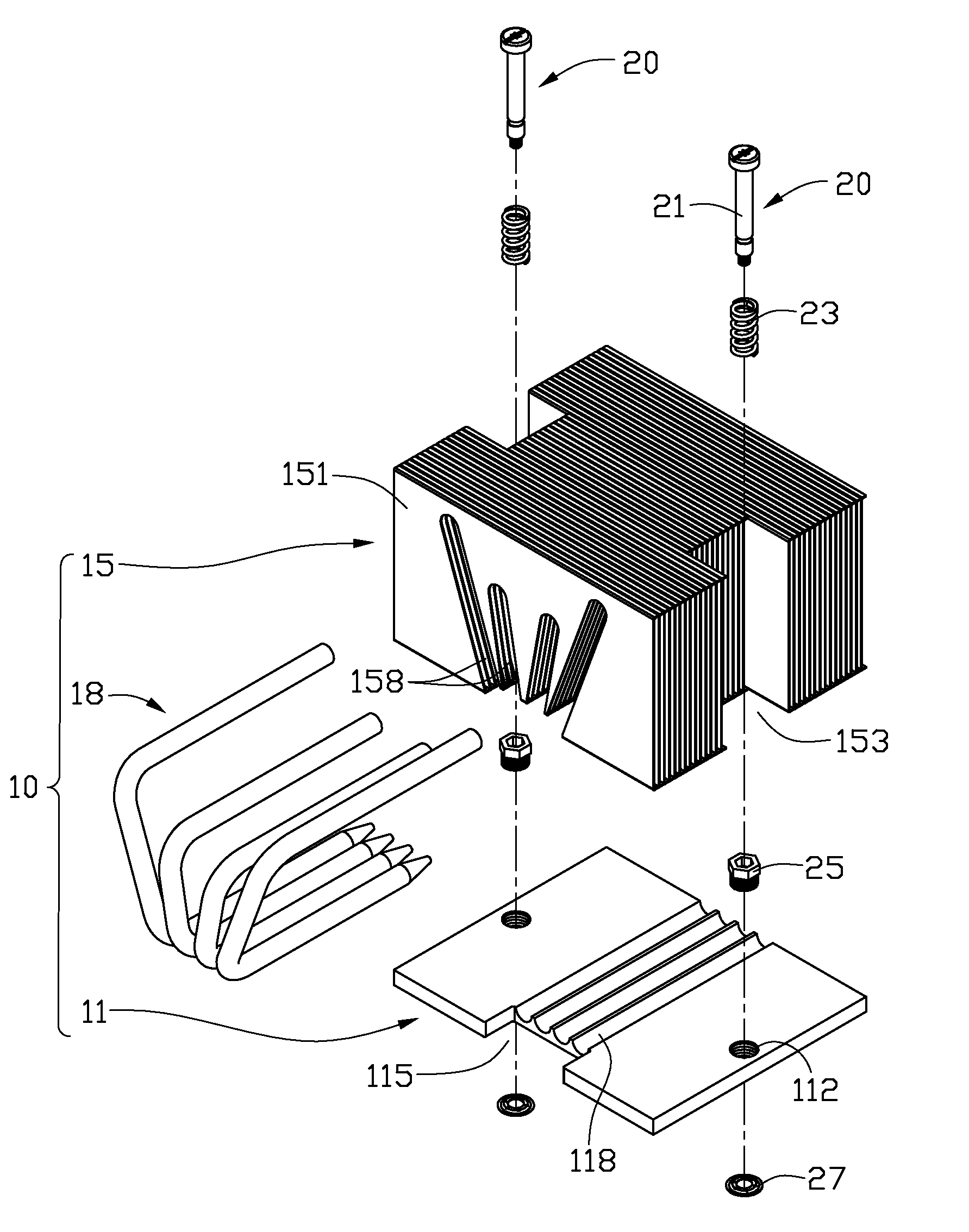
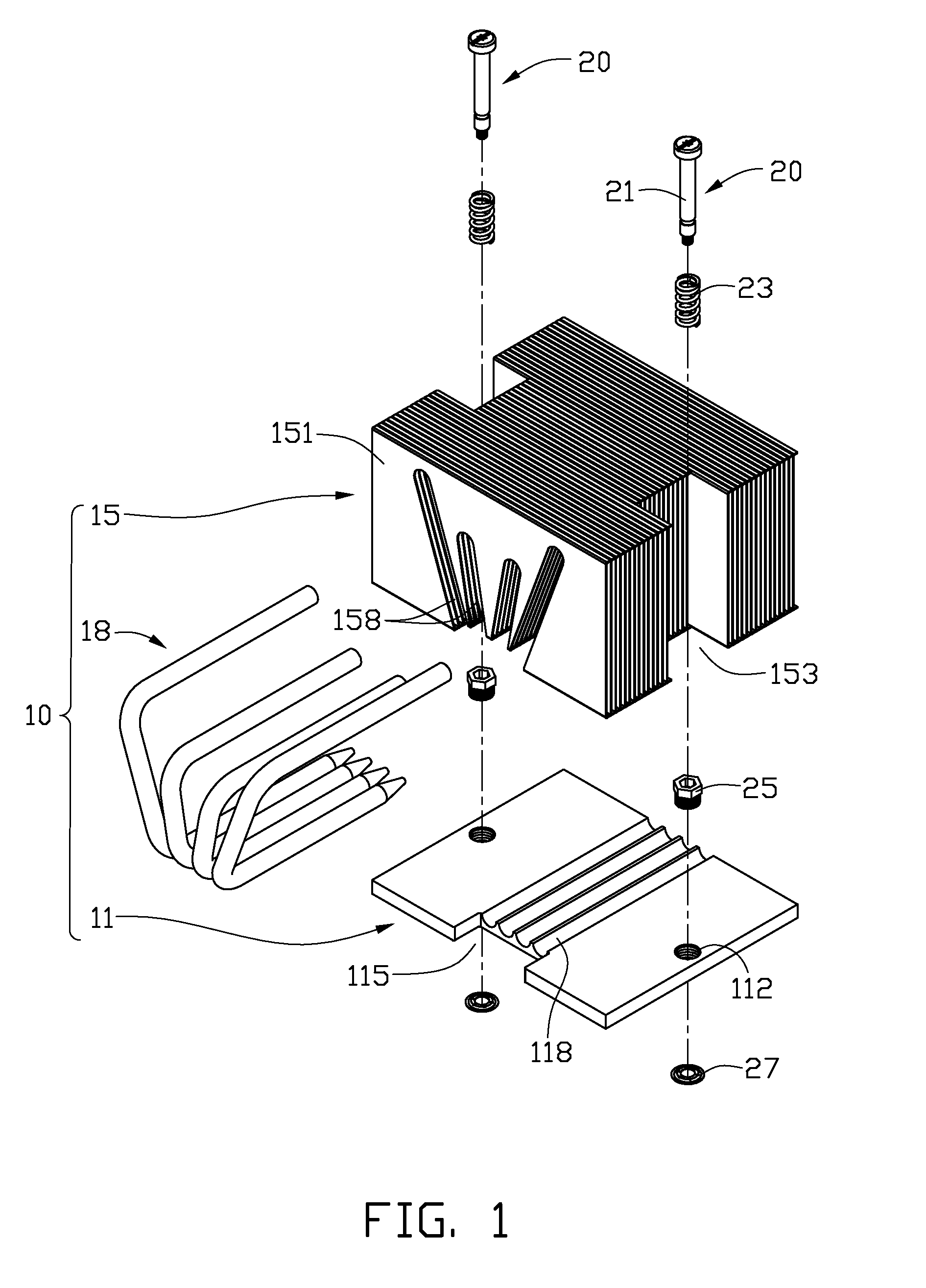
[0015]Referring to FIG. 1, a heat dissipation device of a preferred embodiment is shown. The heat dissipation device comprises a heat sink 10, two fasteners 20 for fastening the heat sink 10 to an electronic device (not shown) mounted on a printed circuit board (not shown) and two sleeves 25 engaging with the heat sink 10 and the fasteners 20 for adjusting fastening force of the fasteners 20 to the heat sink 10.

[0016]The heat sink 10 comprises a base 11, a fin set 15 arranged on the base 11 and four heat pipes 18 connecting the base 11 and the fin set 15. The base 11 is a substantially rectangular plate having good heat conductivity. The base 11 defines two thread holes 112 in middles of two lateral opposite portions thereof. The base 11 defines four parallel grooves 118 for receiving the heat pipes 18. A cutout 115 is defined in a front side of the base 11, adjacent to front ends of the four grooves 118. The fin set 15 comprises a plurality of fins 151 assembled together. Each of t...


PUM


Abstract

A heat dissipation device includes a base, a sleeve coupling with the base, and a fastener engaging with the base and the sleeve. The base defines a hole extending therethrough. The sleeve includes a first portion coupling with the hole of the base and a second portion extending from an end of the first portion. The second portion is located at a first side of the base. The fastener includes a body portion extending through the sleeve and the base, a head portion and a foot portion formed at two ends of the body portion, respectively. The head portion is located at the first side of the base. A spring member is compressed between the head portion and the second portion. A compressed length of the spring member is adjustable by adjusting a coupling length of the first portion with the hole of the base.

Description

BACKGROUND OF THE INVENTION [0001]1. Field of the Invention[0002]The present invention relates to a heat dissipation device, and particularly to a heat dissipation device with a fastener for fastening the heat dissipation device to an electronic device.[0003]2. Description of Related Art[0004]It is well known that, during operation of a computer, electronic devices such as central processing units (CPUs) frequently generate large amounts of heat. The heat must be quickly removed from the electronic device to prevent it from becoming unstable or being damaged. Typically, heat dissipation device including a heat sink is attached to an outer surface of the electronic device to absorb heat from the electronic device. The heat absorbed by the heat sink is then dissipated to ambient air.[0005]In order to keep the heat sink in intimate contact with the electronic device, the heat dissipation device includes a fastener engaging with a printed circuit board where the electronic device is loc...

Claims


Application Information

Patent Timeline
Patent Type & Authority Applications(United States)
IPC IPC(8): F28F7/00
CPCF28D15/0266F28F1/32H01L23/4006H01L23/427H01L23/467H01L2924/0002F28D15/0275H01L2924/00
Inventor ZHENG, DONG-BOFU, MENGCHEN, CHUN-CHI
Owner FU ZHUN PRECISION IND SHENZHEN
Why Eureka
Try Eureka