Head-mountable cockpit display system

a display system and cockpit technology, applied in the field of electronic display systems, can solve the problems of increased cost, inability to meet the needs of users, inconvenient installation,

Active Publication Date: 2010-01-07
HONEYWELL INT INC
View PDF25 Cites 56 Cited by
  • Summary
  • Abstract
  • Description
  • Claims
  • Application Information

AI Technical Summary

Benefits of technology

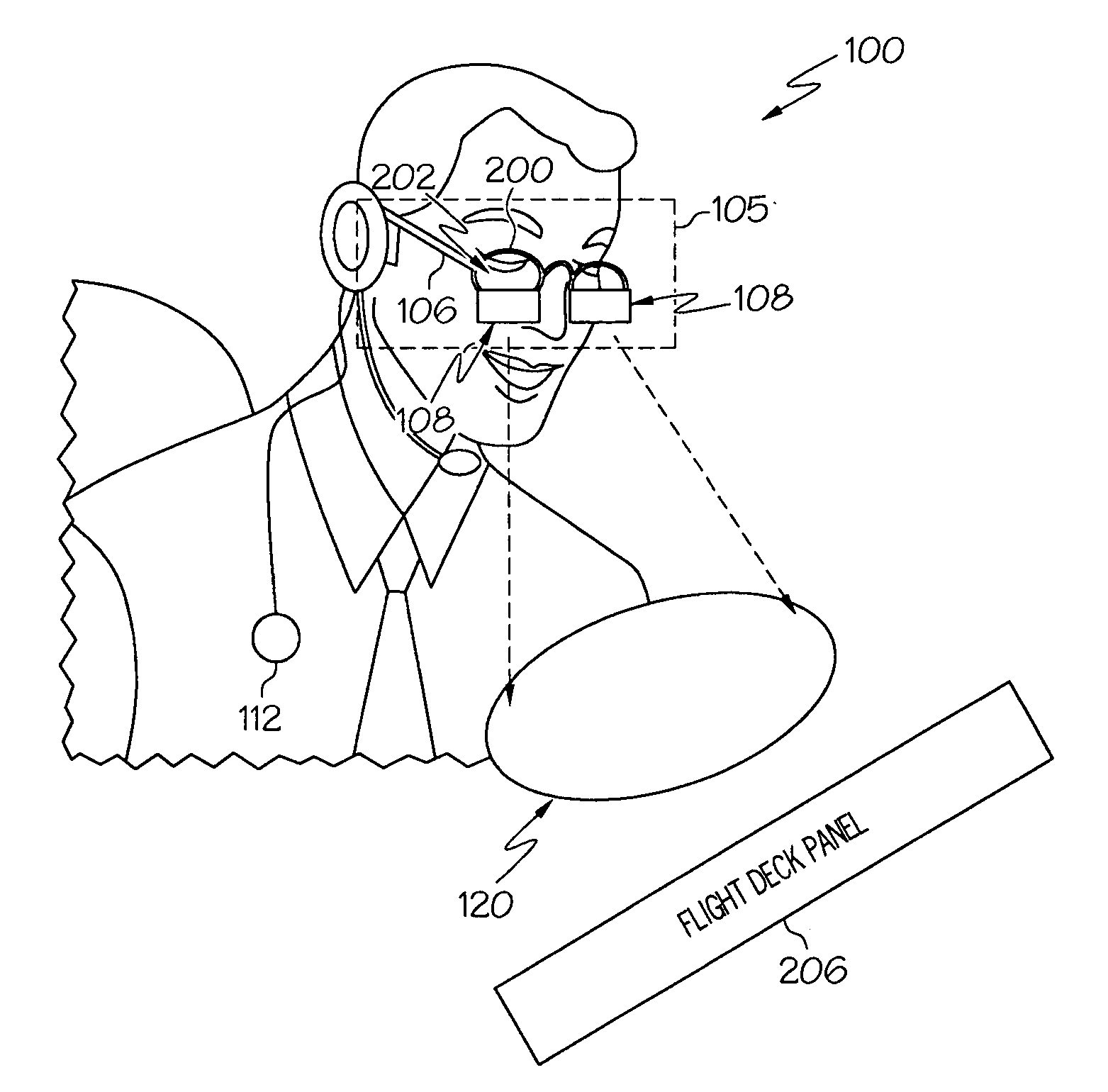
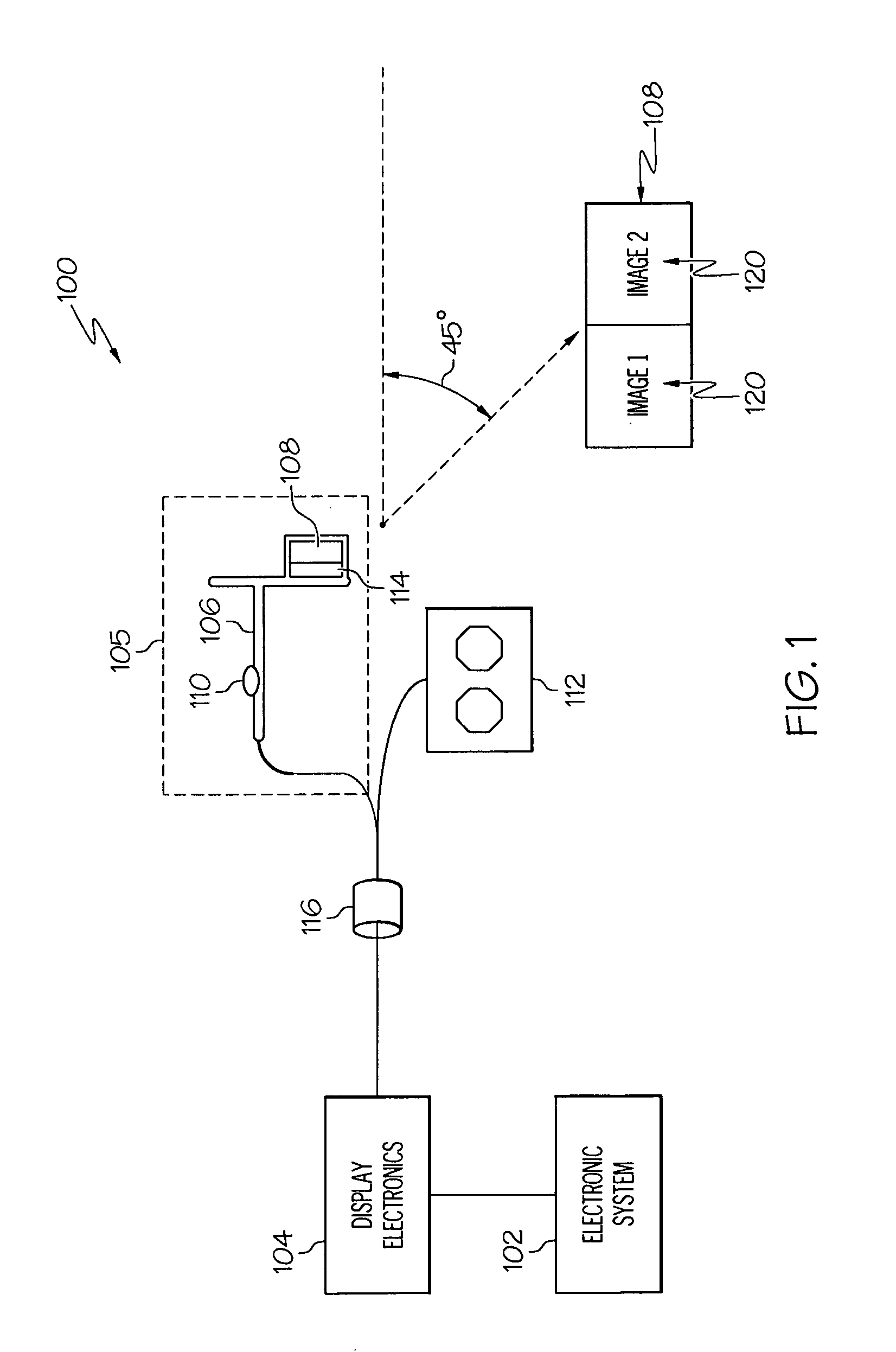
[0006]An apparatus is provided for a head-mountable device suitable for wearing during operation of an aircraft. The head-mountable device comprises an eyeglass frame adapted to be worn on the head of a user. The eyeglass frame defines a field of view aligned with the eyes of the user, wherein the field of view is substantially transparent. A display element is supported by the eyeglass frame and obstructs a lower portion of the field of view. A display controller is coupled to the display element, and the display controller is configured to control rendering of an image on the display element, wherein the image contains information associated with operation of the aircraft, and present the image rendered on the display element as a wide-angle image.

Problems solved by technology

These display systems are generally expensive to build and install.
While these costs may be acceptable for high-end commercial or military deployments, in the case of smaller aircraft, the added cost is often unacceptable and / or impractical.
For example, smaller aircraft typically have smaller space available within the cockpit, and therefore result in additional size and / or positioning constraints when trying to accommodate a smaller flight deck.
Once the electronic display systems are installed, they are difficult to modify or adjust (e.g., size, shape, positioning).
Furthermore, the added costs and difficulties become even greater when retrofitting an aircraft.
As a result, head-up displays are often complex and costly.
Additionally, the size and / or robustness of the projected image is often governed by the size limitations of the display element (e.g., combiner, bezel, visor, lens).
Therefore, many of these displays are generally constrained to a limited symbology and limited flight information (e.g., airspeed, altitude), and still require panel mounted displays in the cockpit or flight deck to provide additional flight information (e.g., maps, engine parameters, aircraft monitoring).
Thus, while available head-mounted displays may be suitable for replacing displays related to basic flight information, they are inadequate for the purposes of replacing and / or simulating a glass cockpit and many of the traditional panel mounted electronic display systems.

Method used


Image

  • Head-mountable cockpit display system
  • Head-mountable cockpit display system
  • Head-mountable cockpit display system

Examples


Embodiment Construction

[0011]The following detailed description is merely exemplary in nature and is not intended to limit the subject matter of the application and uses thereof. Furthermore, there is no intention to be bound by any theory presented in the preceding background or the following detailed description.

[0012]Techniques and technologies may be described herein in terms of functional and / or logical block components, and with reference to symbolic representations of operations, processing tasks, and functions that may be performed by various computing components or devices. It should be appreciated that the various block components shown in the figures may be realized by any number of hardware, software, and / or firmware components configured to perform the specified functions. For example, an embodiment of a system or a component may employ various integrated circuit components, e.g., memory elements, digital signal processing elements, logic elements, look-up tables, or the like, which may carry...


PUM


Abstract

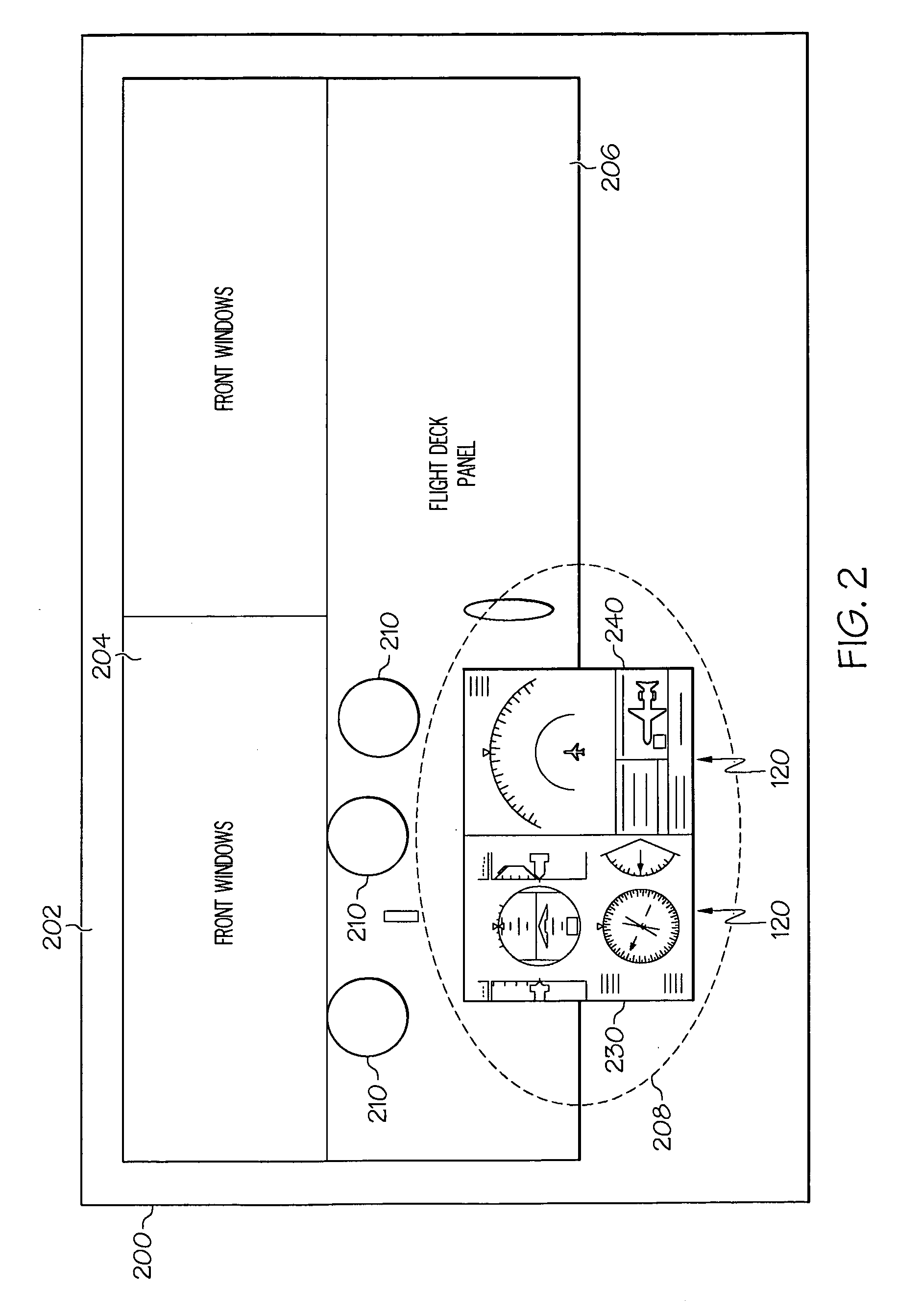
Systems and apparatus are provided for head-mountable cockpit displays for providing information related to an aircraft system to a user. A cockpit display system comprises an eyeglass frame adapted for wearing on the head of the user. The eyeglass frame has a perimeter defining a field of view. A display element is mechanically coupled to the eyeglass frame and aligned with a bottom portion of the field of view. Display electronics are coupled to the display element, and an avionics system is coupled to the display electronics. The display electronics are configured to render an image of a cockpit instrument panel associated with the avionics system on the display element.

Description

TECHNICAL FIELD[0001]The subject matter described herein relates generally to electronic display systems, and more particularly, embodiments of the subject matter relate to methods and systems for head-mountable display systems for simulating a cockpit instrument panel in an aircraft.BACKGROUND[0002]Electronic cockpit displays (e.g., glass cockpits) have replaced traditional mechanical gauges and utilize computerized or electronic displays to graphically convey information related to various electronic systems associated with the electronic display. Typically, there may be as many as six or more electronic displays in most large aircraft (e.g., commercial or military aircraft), and as many as three or more electronic displays in smaller aircraft (e.g., private aircraft). These display systems are generally expensive to build and install. While these costs may be acceptable for high-end commercial or military deployments, in the case of smaller aircraft, the added cost is often unacc...

Claims


Application Information

Patent Timeline
Patent Type & Authority Applications(United States)
IPC IPC(8): G09G5/00
CPCG02B27/017G02B27/0172G02B2027/014G02B2027/0123G02B2027/0118
Inventor NUTARO, JOSEPH
Owner HONEYWELL INT INC
Why Eureka
Try Eureka