Device for applying liquid coating materials

Inactive Publication Date: 2010-01-14
ROBERT BOSCH GMBH
3 Cites 2 Cited by

AI-Extracted Technical Summary

Problems solved by technology

It is especially difficult to stay within paint application boundaries whenever different colors of paint in special f...

Method used

[0027]The nozzle plates 4, although this cannot be seen from the views in FIGS. 1 and 2, are preferably fixed replaceably to the housing 2 and in particular are braced, for instance in sliding guides of the side walls of the housing 2; the particular working position of the nozzle plate 4 can be secured by a lock, in particular a snap closure. Disposing the nozzle plate 4 that contains the nozzle openings 5 detachably ...

Benefits of technology

[0035]Overall, the device 1 thus proves to be a lightweight handheld power tool that in particular can be operated with good resul...

Abstract

The invention relates to a device (1) for applying liquid coating materials, particularly paints, onto an application surface (8), comprising an ejection system (11) for the coating material, wherein the coating material is fed to a displacement chamber (12), is applied in the displacement chamber (12) by means of a displacement element (13), is fed from the displacement chamber (12) to a throttle (26) in metered doses and is then forcefully ejected via the throttle opening (5) thereof against the application surface (8) in the form of droplets.

Application Domain

Technology Topic

EngineeringThrottle opening +2

Image

  • Device for applying liquid coating materials
  • Device for applying liquid coating materials
  • Device for applying liquid coating materials

Examples

  • Experimental program(1)

Example

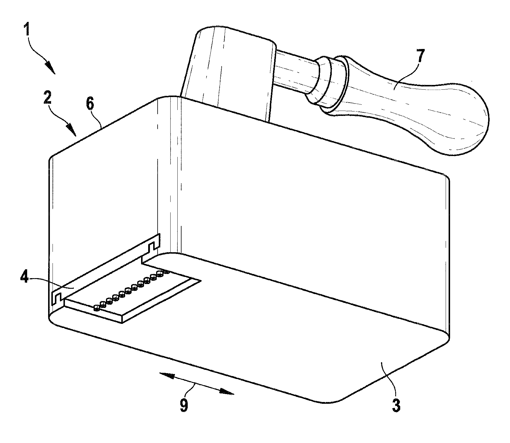
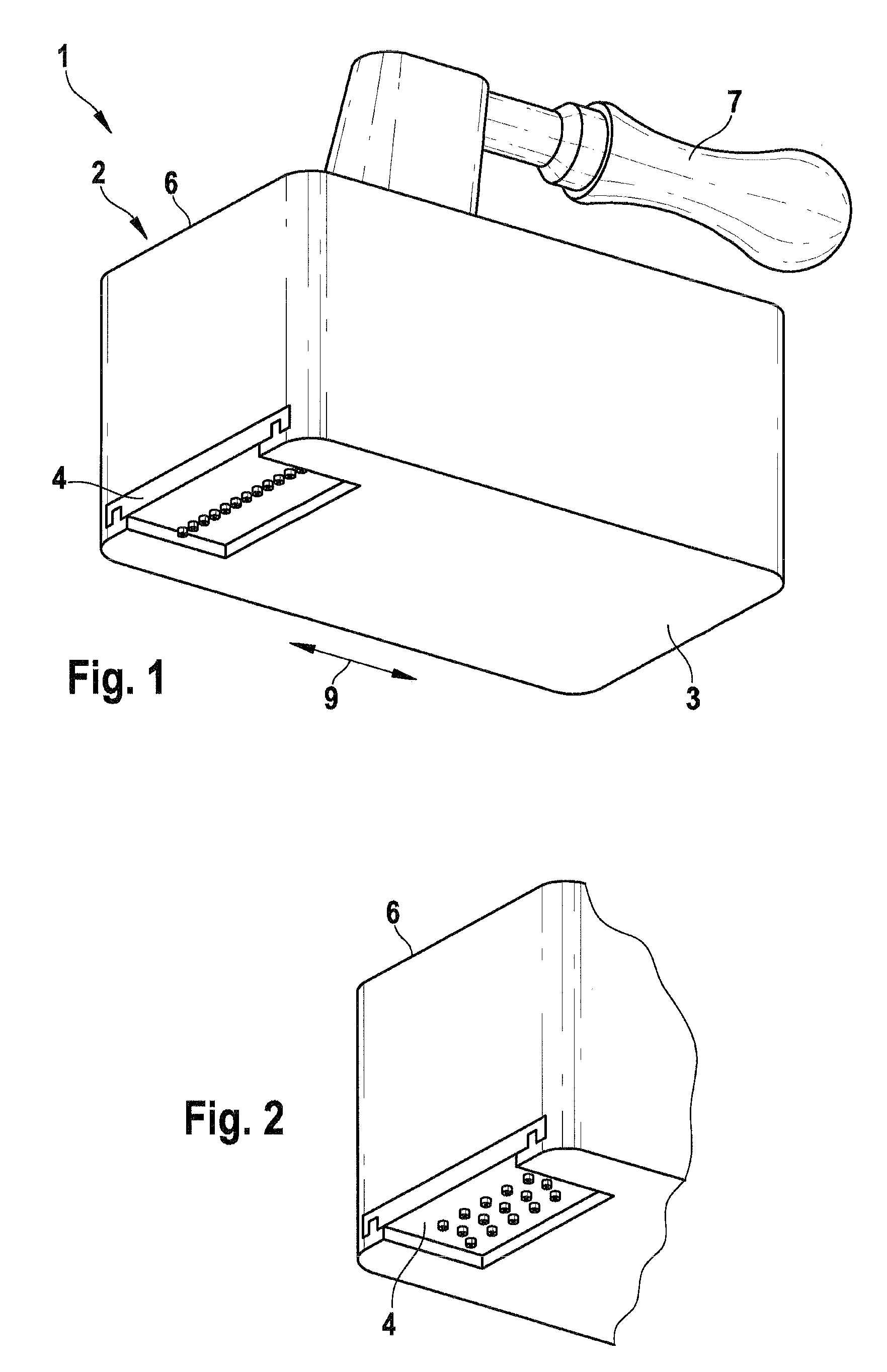
[0024]The housing 2 of the device 1, in its bottom 3, has an inserted nozzle plate 4 with nozzle openings 5. On the top side 6, diametrically opposite the bottom 3, the device 1 is provided with a handle 7.
[0025]In principle, the handle 7 may also be provided laterally of the device 1. Although this is not shown, the device 1 is expediently provided in the region of the bottom 3, and optionally also laterally cantilevered relative to the bottom 3, with supporting elements, such as rollers, wheels, or the like, by way of which a preferred working spacing from the application surface 8, indicated in FIG. 8, can be set and adhered to as a minimum spacing.
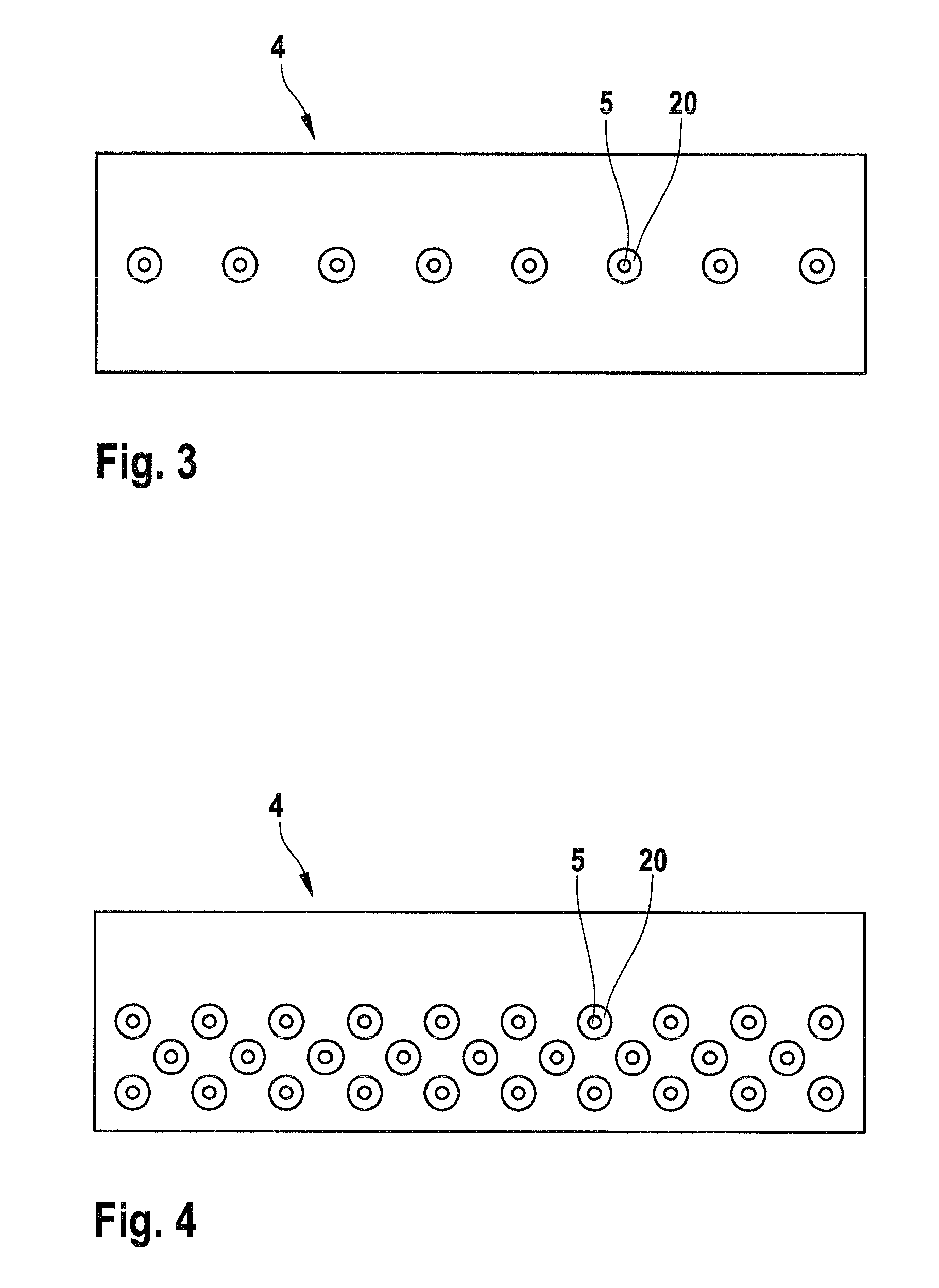
[0026]FIGS. 1 through 4 show that the device 1 can be operated in conjunction with various arrangements of nozzle openings 5; FIG. 3, corresponding to FIG. 1, shows an arrangement of the nozzle openings 5 in one row, while FIG. 4 in conjunction with FIG. 2 shows an arrangement of nozzle openings 5 in a plurality of rows. The rows of nozzle openings 5 each extend transversely to a working direction symbolized by the arrow 9.
[0027]The nozzle plates 4, although this cannot be seen from the views in FIGS. 1 and 2, are preferably fixed replaceably to the housing 2 and in particular are braced, for instance in sliding guides of the side walls of the housing 2; the particular working position of the nozzle plate 4 can be secured by a lock, in particular a snap closure. Disposing the nozzle plate 4 that contains the nozzle openings 5 detachably relative to the housing 2 also makes it possible in particular to detach the nozzle plate 4 from the housing 2 for cleaning purposes, so that not only the replacement of nozzle plates 4 variously equipped with nozzle openings 5, but also simple and fast maintenance of the device 1 are assured, which is of major practical importance for working with coating materials, such as paints in particular, like dispersion paints.
[0028]Via the nozzle openings 5, the particular liquid coating material, thus in particular a given paint, is applied to the application surface 8; the coating material is expelled in the form of droplets—droplets 10 are indicated in FIG. 8—in the direction of the application surface 8 and also in droplet form strike the application surface 8, where the droplets 10 join to form a covering, in particular a closed, filmlike layer of paint, that covers the application surface 8. The paint layer thus achieved is equivalent in the end and in quality to at least that when paint is applied with brushes, rollers or the like, but also makes continuous work possible without soiling the surroundings, either from paint spatters or paint spray, since the droplet structure of closed circumference, defined upon expulsion via the nozzles 26, of the coating material is maintained until it strikes the application surface 8, and on the application surface 8, the droplets 26 merely flatten, in accordance with the layer thickness sought, and with the droplets adjoining them form a closed covering layer.
[0029]This is achieved with an expulsion system 11 as shown in diagram form in FIG. 8 and schematically with associated details, including the associated drive mechanism, in FIGS. 5 through 7. The expulsion system 11 provided in the housing 2, beginning at the applicable nozzle opening 5, includes a positive-displacement chamber 12 communicating with the nozzle opening, into which chamber a positive-displacement element 13 plunges that in the exemplary embodiment is designed as a pump plunger 14; on its face end, the pump plunger 14 is adapted in its contour to the domelike contour of the positive-displacement chamber 12 at the transition to the nozzle 26 and its nozzle opening 5. As the inlet for the coating material, an inlet conduit 15 discharges toward the positive-displacement chamber 12; in the exemplary embodiment, this conduit laterally adjoins the positive-displacement chamber 12, and discharges, when the pump plunger 14 plunges into the dome 16 of the positive-displacement chamber 12, at an rr 17, which is defined radially inward in this region by means of a reduction of the circumference of the positive-displacement element 13. In the guide region for the pump plunger 14, which region tapers toward the dome 16, the pump plunger is guided in the bore 18 receiving it, so that the positive-displacement chamber 12 is axially sealed off by way of the part of the pump plunger 14 that extends within the guide bore 18.
[0030]At the apex, the dome 16 is in communication with the nozzle opening 5; in the exemplary embodiment, this communication is formed by a capillary that continues on into the nozzle opening 5, and the nozzle opening 5 is surrounded by a nozzle collar 20 that projects past the bottom of the nozzle plate 4 and comes to an end as a thin-walled, tubular projection, preferably in bladelike fashion, optionally widening in the direction of the blade, so that the droplet 10 detaches without residue from the guide formed by the capillary. if the spacing between the nozzle opening 5 and the positive-displacement chamber 12 is reduced to the minimum necessary for reasons of strength, the result for the capillary 19 is a very short length, but depending on the type of coating material to be handled, especially its viscosity, greater lengths may optionally be specified for the capillary 19 instead, depending on its diameter.
[0031]Via the pump plunger 14, in its working stroke, the coating material is expelled from the positive-displacement chamber 12 in the direction of the nozzle opening 5, as is shown in FIG. 6. If the pump plunger 14 is retracted, then the positive-displacement chamber 12 becomes larger and is filled via the inflow conduit 15; the inflow of coating material via the inflow conduit 15 to the positive-displacement chamber 12 preferably takes place at pilot pressure, in particular a slight pilot pressure of a few bar, so that depending on the operating frequency of the pump plunger 14, and given free communication between the inflow conduit 15 and the positive-displacement chamber 12, a medium pressure is established, at which the coating material is positively displaced in the direction of the nozzle opening 5 and expelled via the nozzle opening 5. The nozzle opening 5 and the positive-displacement chamber 12, with an adjoining guide part 21 for the pump plunger 14 that is sealed off via the pump plunger 14, are located inside the nozzle plate 4, as shown in FIGS. 5 and 6. The drive for the pump plunger 14, including a linear guide for the pump plunger 14, is braced inside the housing 2 independently of the nozzle plate 4, given a corresponding alternating orientation. The linear guide for the pump plunger 14 is indicated at 22 in FIG. 8, and as the drive for the pump plunger 14, an eccentric or crank drive 23 is provided, whose eccentric or crank arm 24 is connected via a connecting rod 25 to the pump plunger 14 extending in the linear guide 22, so that the drive originating at the motor, not shown, takes the overall form of a thrust crank drive acting on the pump plunger 14.
[0032]This kind of mechanical drive proves expedient for the pump plunger in view of the operating frequencies on the order of magnitude of approximately 100 Hz that are sought, in order to make do with as small as possible a drive unit; in principle, one such drive unit may be associated with each pump plunger 14.
[0033]However, as a common drive for a plurality of pump plungers 14, a drive source may be provided that drives an eccentric or crank shaft, whose eccentric elements or cranks are each connected to one pump plunger 14. Moreover, a common drive for a plurality of pump plungers 14 may include a supporting beam connected to the pump plungers 14, which is acted upon via an eccentric or crank drive. In particular, the pump plungers 14 associated with the nozzles 26 of a row of nozzle openings 5 can thus also be driven in common.
[0034]A common supply is expediently provided for the positive-displacement chambers 12, which communicate with one another via corresponding inflow conduits 15 that in turn are connected to a supply reservoir for the coating material, which may be located inside the housing 2, so that the device is an independent handheld work device. Optionally, the device 1 may also be in communication with an external supply container, and it proves expedient to associate at least one temporary storage means with the device 1 in encapsulated fashion in the housing 2, so that as needed, for instance depending on position, work is still possible even independently of the external supply container. For the eccentric or crank drive, an electric motor, which is not shown, is preferably provided, integrated with the device 1 and in particular located in the housing 2.
[0035]Overall, the device 1 thus proves to be a lightweight handheld power tool that in particular can be operated with good results even by relatively inexperienced users, and for driving it, hydraulic or pneumatic drives, among others, may also be considered.
[0036]For the embodiment of the device, particularly with regard to the diameter of the pump plunger 14, dimensions of 1 to 3 mm, preferably approximately 2.5 mm, prove expedient; also, the stroke of the pump plunger 14 is preferably approximately 1 to 10 mm, in particular 7 mm, and the frequency of the pump plunger 14 is approximately 50 to 120 Hz, in particular 100 Hz. The inflow pressure is preferably approximately 0.5 to 1.5 bar, and particularly in the range around 1 bar. For the capillaries, diameters of approximately 0.3 to 0.6 mm, and preferably approximately 0.4 mm, prove expedient; the length of the capillary is in particular in the range of 0.5 to 6 mm. For the droplets, droplet diameters of approximately 1.5 to 3 mm, and in particular approximately 2.2 mm, prove expedient in order to achieve a uniform coating, and in particular a uniformly covering application of paint.

PUM

no PUM

Description & Claims & Application Information

We can also present the details of the Description, Claims and Application information to help users get a comprehensive understanding of the technical details of the patent, such as background art, summary of invention, brief description of drawings, description of embodiments, and other original content. On the other hand, users can also determine the specific scope of protection of the technology through the list of claims; as well as understand the changes in the life cycle of the technology with the presentation of the patent timeline. Login to view more.

Similar technology patents

Method and device for selecting hyperspectral image band based on key band extraction

ActiveCN106778680AImprove Band Selection EfficiencyGood resultCharacter and pattern recognitionBand selectionSpectral image
Owner:HANGZHOU DIANZI UNIV

Classification and recommendation of technical efficacy words

Why Eureka
Try Eureka