

Decorative lighting apparatus
- Summary
- Abstract
- Description
- Claims
- Application Information
AI Technical Summary
Benefits of technology
Problems solved by technology
Method used
Image

Examples
first embodiment
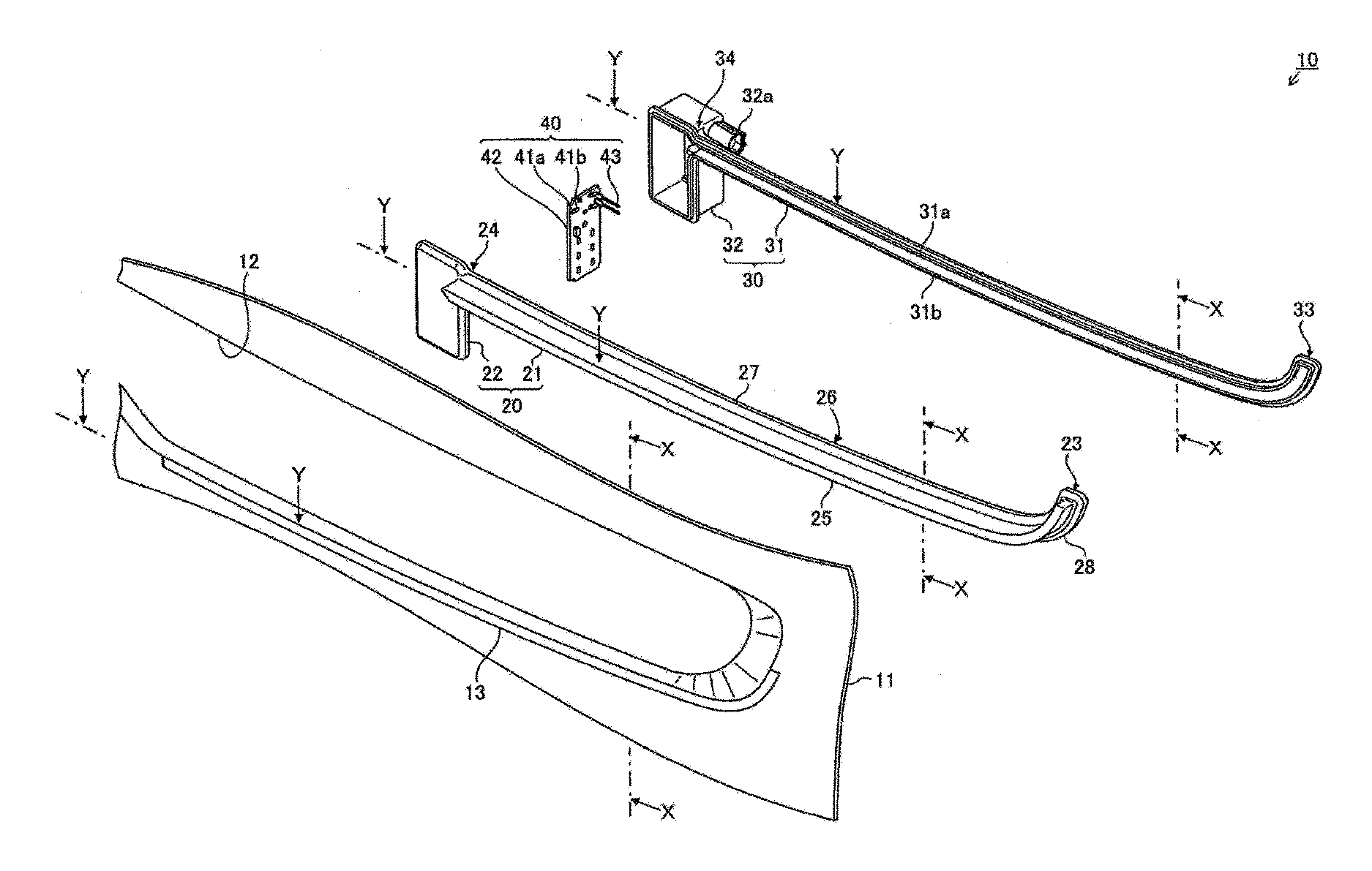
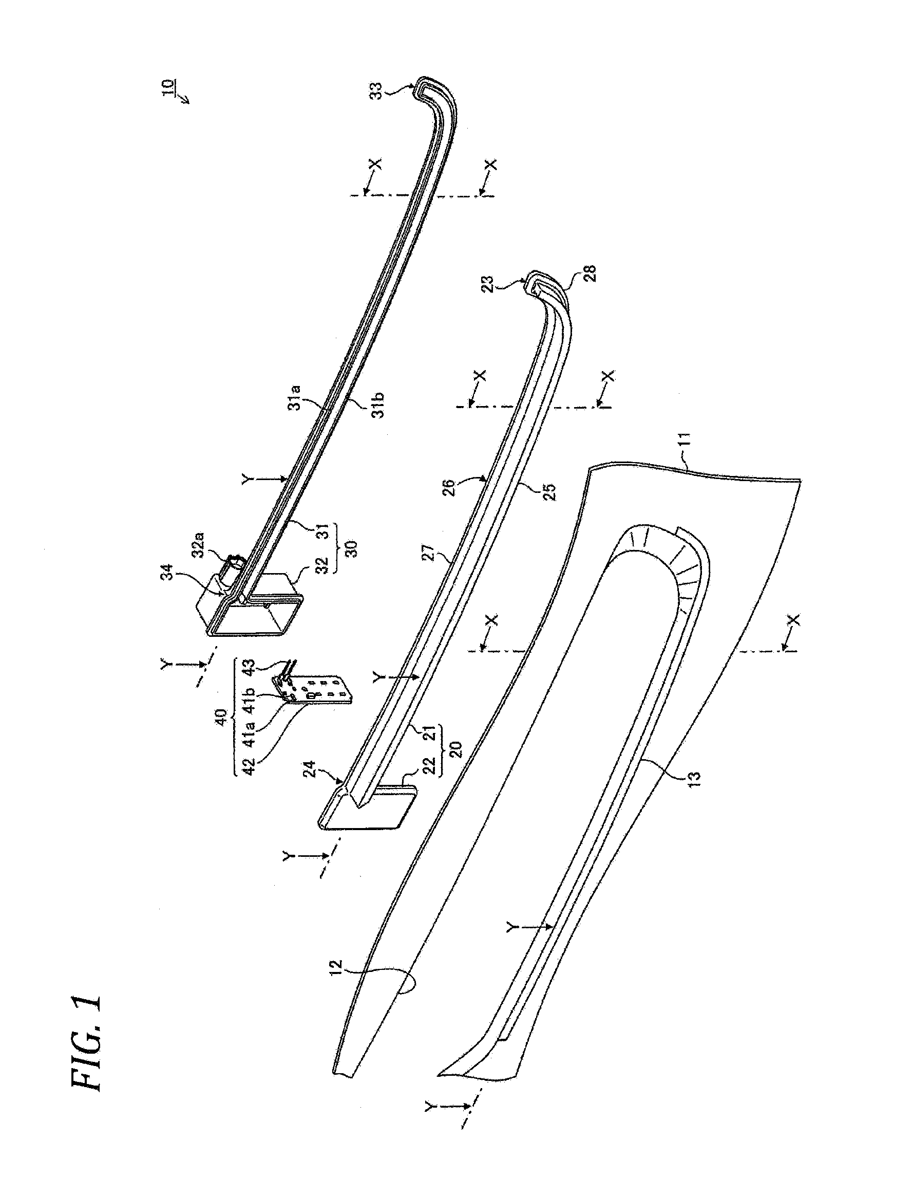
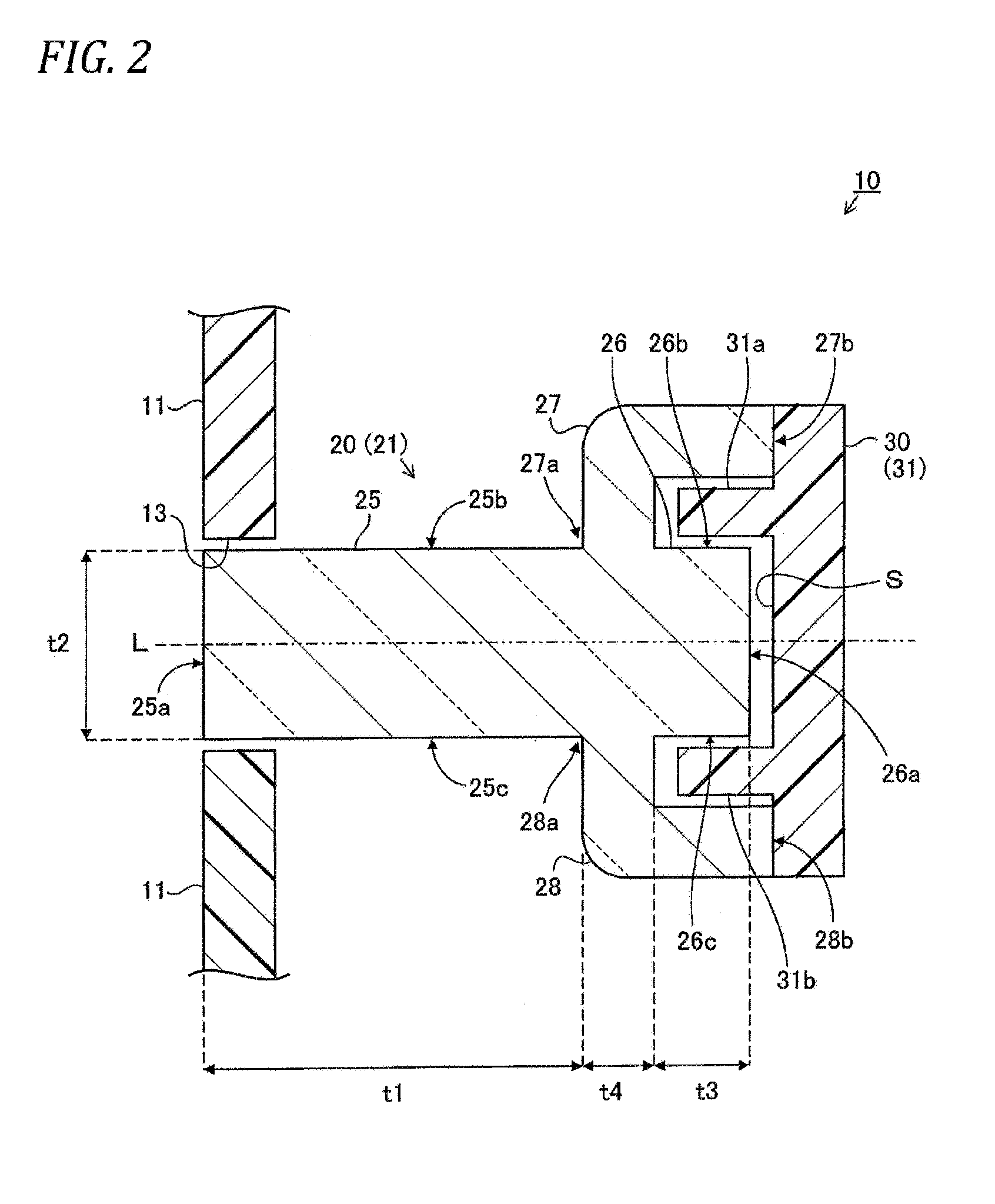
[0041]As illustrated in FIGS. 1 to 3, a decorative lighting apparatus 10 for a vehicle includes a front grill 11, a grill opening 12, an installation hole 13, an outer lens 20, a body part 21, a cover part 22, a distal end 23, a proximal end 24, a surface protrusion 25 (surface 25a, sides 25b and 25c), a back protrusion 26 (back 26a, sides 26b and 26c, proximal end surface 26d, light introduction part 26e), a first connection part 27 (one end 27a, the other end 27b), a second connection part 28 (one end 28a, the other end 28b), a housing 30, a body part 31 (projections 31a and 31b), an accommodation part 32 (connector 32a), a distal end 33, a proximal end 34, a light source 40, LEDs 41a and 41b, a wiring board 42, a connection terminal 43, a cavity S and the like.
[0042]The front grill (radiator grill) 11 has the shape of an elongated plate that is long laterally and forms a design surface of a front portion of a vehicle, and has a bilateral symmetric structure when viewed from a fr...
second embodiment
[0137]As illustrated in FIG. 4, a decorative lighting apparatus 100 for a vehicle includes a front grill 11, a grill opening 12, an installation hole 13, an outer lens 20, a body part 21, a surface protrusion 25 (surface 25a, sides 25b and 25c), a back protrusion 26 (back 26a, sides 26b and 26c), a first connection part 27 (one end 27a, the other end 27b), a second connection part 28 (one end 28a, the other end 28b), a housing 30, a body part 31 (projections 31a and 31b), a cavity S, outer circumferential walls 101a and 101b and the like.
[0138]Although not illustrated in FIG. 4, the decorative lighting apparatus 100 for the vehicle according to the second embodiment includes the same members as other members of the decorative lighting apparatus 10 for the vehicle according to the first embodiment.
[0139]The decorative lighting apparatus 100 for the vehicle according to the second embodiment is different from the decorative lighting apparatus 10 for the vehicle according to the first...
third embodiment
[0146]As illustrated in FIG. 5, a decorative lighting apparatus 200 for a vehicle includes a front grill 11, a grill opening 12, an installation hole 13, an outer lens 20, a body part 21, a surface protrusion 25 (surface 25a, sides 25b and 25c), a back protrusion 26 (back 26a, sides 26b and 26c), a first connection part 27 (one end 27a, the other end 27b), a second connection part 28 (one end 28a, the other end 28b), a housing 30, a body part 31, a cavity S, outer circumferential walls 101a and 101b and the like.
[0147]Although not illustrated in FIG. 5, the decorative lighting apparatus 200 for the vehicle according to the third embodiment includes the same members as other members of the decorative lighting apparatus 10 for the vehicle according to the first embodiment.
[0148]The decorative lighting apparatus 200 for the vehicle according to the third embodiment is different from the decorative lighting apparatus 100 for the vehicle according to the second embodiment in that the pr...
PUM
 Abstract
Description
Claims
Application Information