
Flossing Device With Internal Floss Feed

a flossing device and flossing technology, applied in the field of dental hygiene products, can solve the problems of difficult flossing, clumsy flossing, etc., and achieve the effects of preventing the spread of germs and debris, easy refreshment, and maintaining dental hygiene and health

Inactive Publication Date: 2010-01-21
FILSOUF EHSAN
View PDF20 Cites 3 Cited by
  • Summary
  • Abstract
  • Description
  • Claims
  • Application Information

AI Technical Summary

Benefits of technology

[0009]Dentists recommend regular flossing as one of the best ways to maintain dental hygiene and health. Many people, however, find the act of flossing clumsy and difficult. Flossing by hand requires stretching floss between the fingers of both hands and then working the fingers into the mouth, flossing a given area of the mouth, advancing the floss through the fingers and then flossing another area of the mouth. The advancing of the floss is important in order to prevent the spreading of germs and debris from one area of the mouth to another. By means of the internal mechanism provided by the present invention, the floss is easily refreshed by rotating the floss advance wheel.
[0010]The present invention provides flossing device which has a chamber within its hollow handle in which a spool of floss is stored. The free end of the floss is threaded through an array of feed gears to a pair of tines at the head of the device and back to the take up gears for take up. The floss is maintained taut between the tines of the head for effective flossing. In an alternative embodiment, an electrically operated vibrator is housed in the flossing head to aid in stimulating the gums and removal of dental debris.
[0011]Accordingly, it is a principal object of the invention to provide a flossing device that is easy to use.

Problems solved by technology

Many people, however, find the act of flossing clumsy and difficult.

Method used


Image

  • Flossing Device With Internal Floss Feed
  • Flossing Device With Internal Floss Feed
  • Flossing Device With Internal Floss Feed

Examples


Embodiment Construction

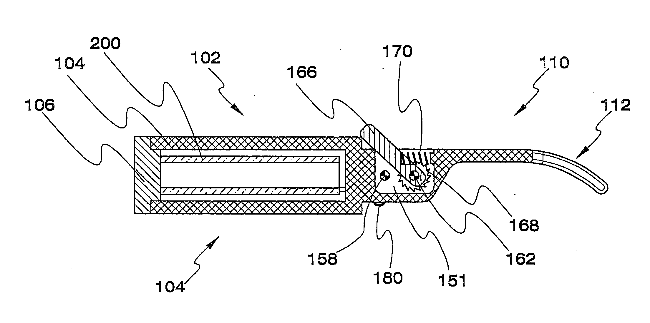
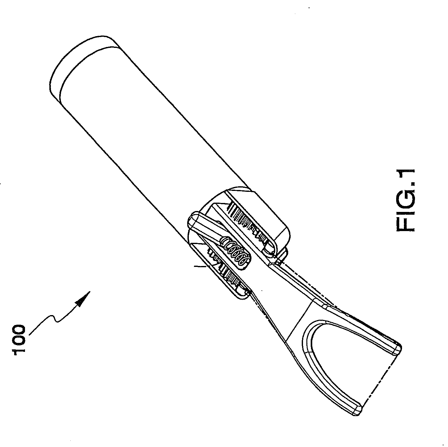
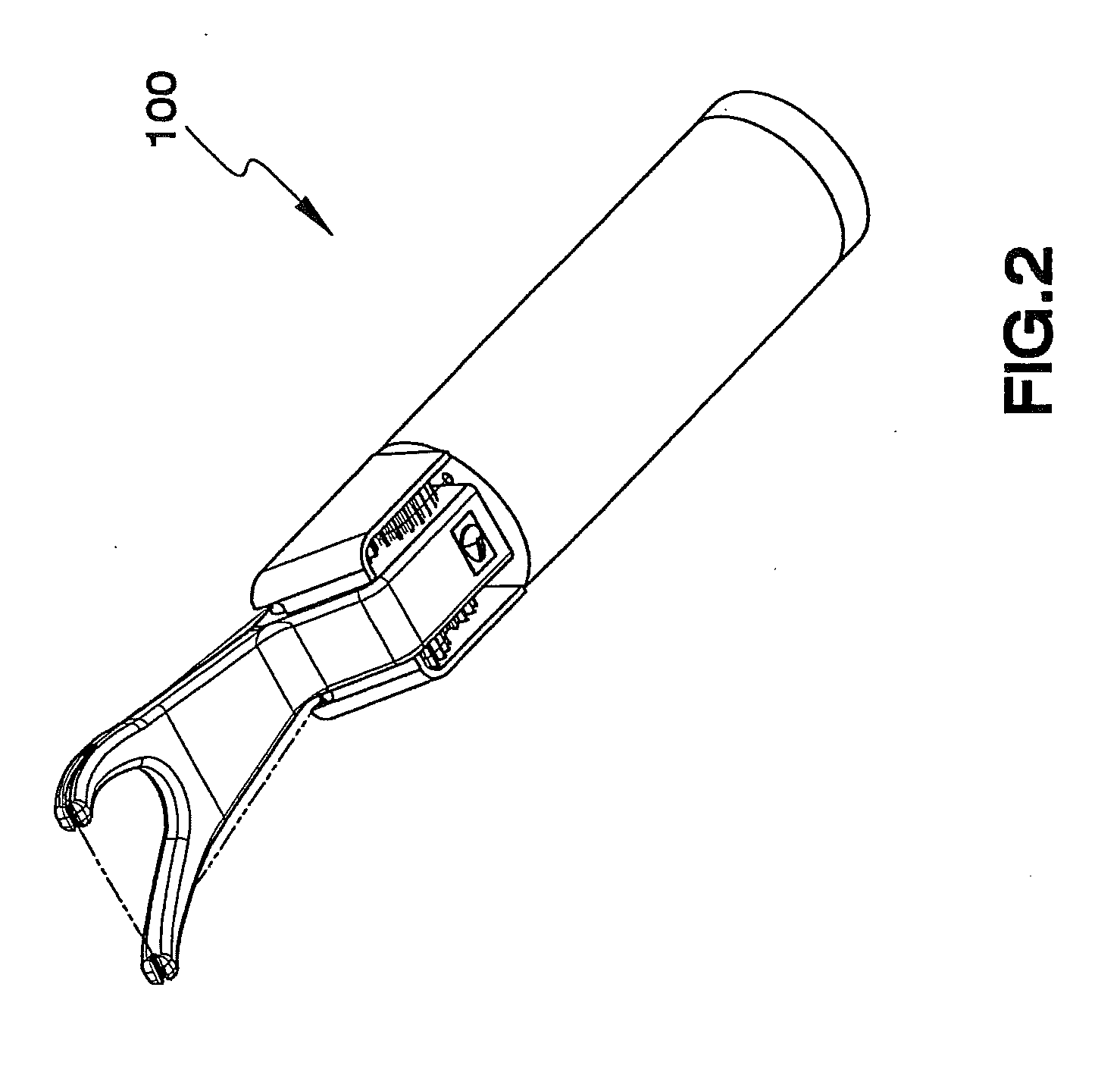
[0042]The flosser 100 of the present invention, as shown in its assembled state at FIGS. 1 and 2, is depicted in further detail at FIGS. 3 through 8.

[0043]The flosser 100 has a body 102 having a hollow handle portion 104 at a first end, handle portion 104 having a threaded cap 106 at a first end of handle portion 104 and a threading aperture 108 at a second end of handle 104. Handle 104 is dimensioned and configured to comfortably fit into a human hand.

[0044]At a second end of body 102 is a head 110, head 110 extending longitudinally from the second end of handle 104. Head 110 is solid and substantially flat on its upper and lower surfaces, and is dimensioned and configured for the free end of head 110 to comfortably fit within a human mouth. At the free end of head 110 is a pair of tines 112f and 112r which are angled downwardly from the free end of head 110 at an angle which allows easy access to the teeth. (In the preceding and hereinafter, the designation “f” behind a number wil...


PUM


Abstract

A flossing device having internal floss feed in which floss is advanced from a storage chamber inside the handle of the device, through feed gears, to a pair of spaced apart tines. Spent floss is returned through the return gears, the return drive gear having a greater diameter than the feed drive gear, thus ensuring the floss remains taut between the tines. An integral cutter allows the spent floss to be cut off and discarded. The cover over one or both sets of gears may be open at the top and bottom to allow cleaning of the gears. A flexible tile may be included over the aperture through which the floss exits the storage chamber to prevent water incursion therein. A floss advance lever advances the floss by a single action when pressed forward, which creates and maintains sufficient tension on the floss resulting in taut and snug floss between the tines. Optionally, the flossing head has a vibratory device to aid in the flossing action.

Description

CROSS REFERENCE TO RELATED APPLICATIONS[0001]This application is a Continuation-In-Part of Ser. No. 11 / 858,232 filed on Sep. 20, 2007, now allowed.BACKGROUND OF THE INVENTION[0002]1. Field of the Invention[0003]The present invention relates to dental hygiene products. More particularly, the invention comprises a flossing device with internal storage of floss and an internal feed mechanism for progressing fresh floss through the flossing head.[0004]2. Description of the Prior Art[0005]Numerous flossing devices have been disclosed over the years, may with internal storage for the floss, and many of those with feed mechanisms for advancing the floss through the flossing tines.[0006]Of particular note are U.S. Pat. No. 6,526,994 to Santoro on Mar. 4, 2003; U.S. Pat. No. 5,823,207 to Bushman on Oct. 20, 1998; U.S. Pat. No. 5,947,133 to Kossal, et al., on Sep. 7, 1999; U.S. Pat. No. 5,816,271 to Urso on Oct. 6, 1998; and U.S. Pat. No. 5,269,331 to Tanriverdi on Dec. 14, 1993.[0007]In each...

Claims


Application Information

Patent Timeline
IPC IPC(8): A61C15/04
CPCA61C15/046
Inventor FILSOUF, EHSAN
Owner FILSOUF EHSAN
Learn More