Wheel suspension

a technology of suspension and wheel, applied in the direction of suspension arms, resilient suspensions, vehicle components, etc., can solve the problem of losing the value of the lateral force potential of tires

Inactive Publication Date: 2010-01-21
ZF FRIEDRICHSHAFEN AG
View PDF7 Cites 9 Cited by
  • Summary
  • Abstract
  • Description
  • Claims
  • Application Information

AI Technical Summary

Benefits of technology

[0010]The purpose of the present invention is to provide a wheel suspension for a motor vehicle, with whic

Problems solved by technology

This, however, has disadvantages when the motor vehicle is driving straight ahead, namely if individual vehicle wheels bounce on one side only, as can happen for example when dri

Method used


Image

  • Wheel suspension
  • Wheel suspension
  • Wheel suspension

Examples


Embodiment Construction

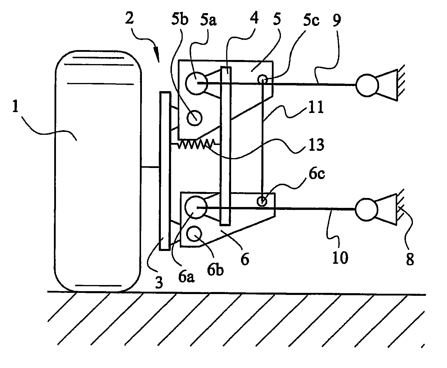
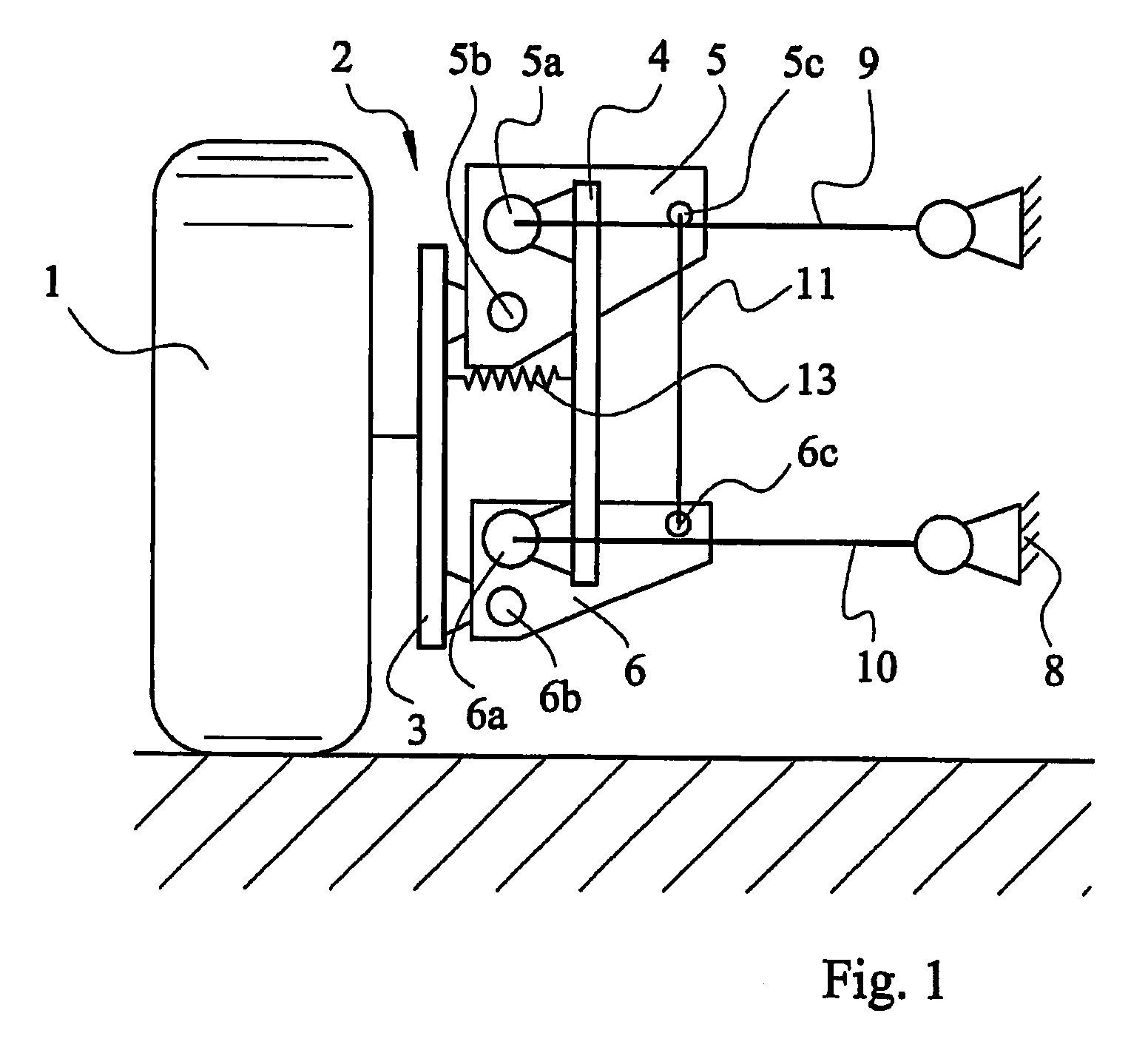
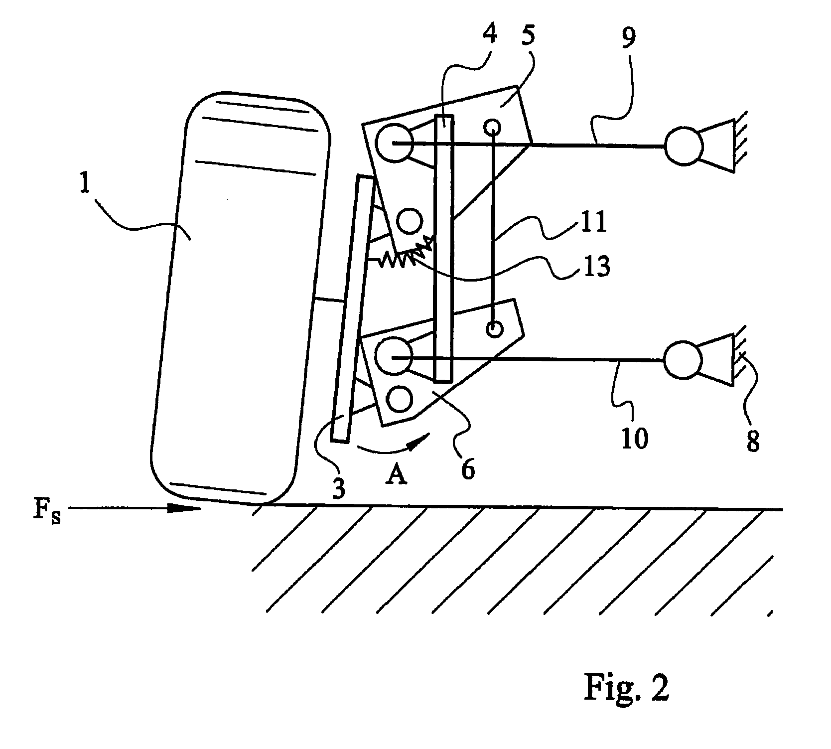
[0029]The first variant of a solution according to the invention, shown in FIGS. 1 and 2, comprises a vehicle wheel 1 mounted to rotate on a wheel carrier indexed, as a whole, as 2. The difference between the representation in FIGS. 1 and 2 is only that FIG. 1 shows a vehicle wheel 1 which is not deflected and FIG. 2 a vehicle wheel 1 which is deflected.

[0030]The wheel carrier 2 consists of a first part 3 with a second part 4 connected thereto. The connection between the parts 3 and 4 of the wheel carrier 2 is formed by two pivoting links 5 and 6 made as wishbones. The wishbones 5 and 6 have in each case three articulation points 5a, 5b, 5c or 6a, 6b, 6c. At least one of the articulation points 5a, 5b, 5c or 6a, 6b, 6c comprises an elastomeric mounting or consists entirely of such an elastomeric mounting.

[0031]The first part 3 of the wheel carrier 2 is connected by a respective articulation 5b, 6b to the wishbones 5 and 6. The second part 4 of the wheel carrier 2, in contrast, is co...


PUM


Abstract

A wheel suspension assembly with a two-part wheel carrier (2) that supports a vehicle wheel (1). A first part (3) of the wheel carrier (2) is articulated to a second part (4) of the wheel carrier (2). Pivoting links (5, 6, 7) connect the first part (3) of the wheel carrier (2) to the second part (4) of the wheel carrier (2) and provide camber and/or tracking adjustment of the vehicle wheel (1).

Description

[0001]This application is a National Stage completion of PCT / DE2007 / 002179 filed Dec. 4, 2007, which claims priority from German patent application serial no. 10 2006 059 778.8 filed Dec. 15, 2006.DESCRIPTION[0002]The invention concerns a wheel suspension.BACKGROUND OF THE INVENTION[0003]For fulfilling the safety and comfort requirements of a motor vehicle, the wheel suspension is a vital structural unit. Accordingly, disturbing influences that act upon the wheel suspension must be optionally compensated. For example, the effect of lateral forces on the vehicle's wheels, as produced when driving round a curve or when the vehicle body rolls, is to change the inclination of a vehicle wheel relative to the road surface. The vehicle wheel camber produced thereby leads to a variation of the tire contact area, so the all-important grip of the vehicle wheel on the ground is diminished.[0004]Previously known dual transverse control arm axles compensate for this camber tendency by controlled...

Claims


Application Information

Patent Timeline
IPC IPC(8): B60G3/26B60G7/00
CPCB60G3/26B60G7/008B60G2200/132B60G2206/50B60G2200/462B60G2204/422B60G2200/46B60G7/00
Inventor ARAMAH, SIMONHEIDSIECK, KNUTHAEUSLER, FELIX
Owner ZF FRIEDRICHSHAFEN AG
Why Eureka
Try Eureka