Fluid deflector for fluid separator devices

a technology of fluid separator and deflector, which is applied in the direction of liquid fuel engine, filtration separation, separation process, etc., can solve the problem that the device functions less than ideal under certain operating characteristics

Inactive Publication Date: 2010-01-28
DRESSER RAND CO
View PDF100 Cites 33 Cited by
  • Summary
  • Abstract
  • Description
  • Claims
  • Application Information

AI Technical Summary

Problems solved by technology

Although such static separators are generally effective, such devices function less than ideally under certain operating characteristics.

Method used


Image

  • Fluid deflector for fluid separator devices
  • Fluid deflector for fluid separator devices
  • Fluid deflector for fluid separator devices

Examples


Embodiment Construction

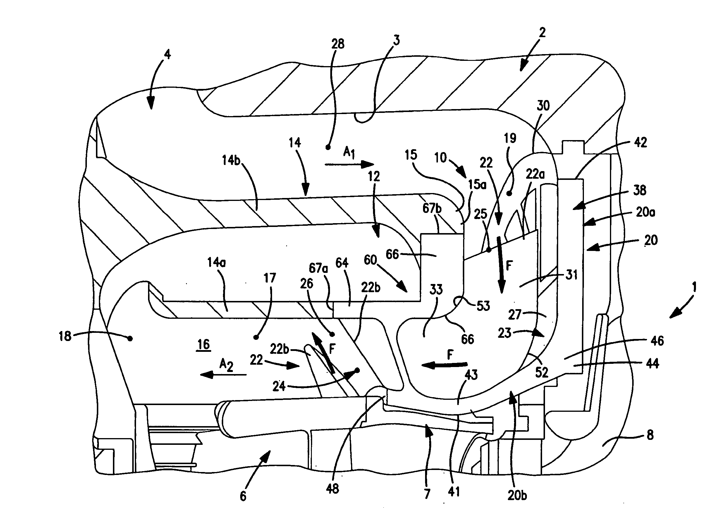
[0025]Certain terminology is used in the following description for convenience only and is not limiting. The words “right”, left”, “lower”, “upper”, “upward”, “down” and “downward” designate directions in the drawings to which reference is made. The words “inner”, “inwardly” and “outer”, “outwardly” refer to directions toward and away from, respectively, a designated centerline or a geometric center of an element being described, the particular meaning being readily apparent from the context of the description. Further, as used herein, the word “connected” is intended to include direct connections between two members without any other members interposed therebetween and indirect connections between members in which one or more other members are interposed therebetween. The terminology includes the words specifically mentioned above, derivatives thereof, and words of similar import.

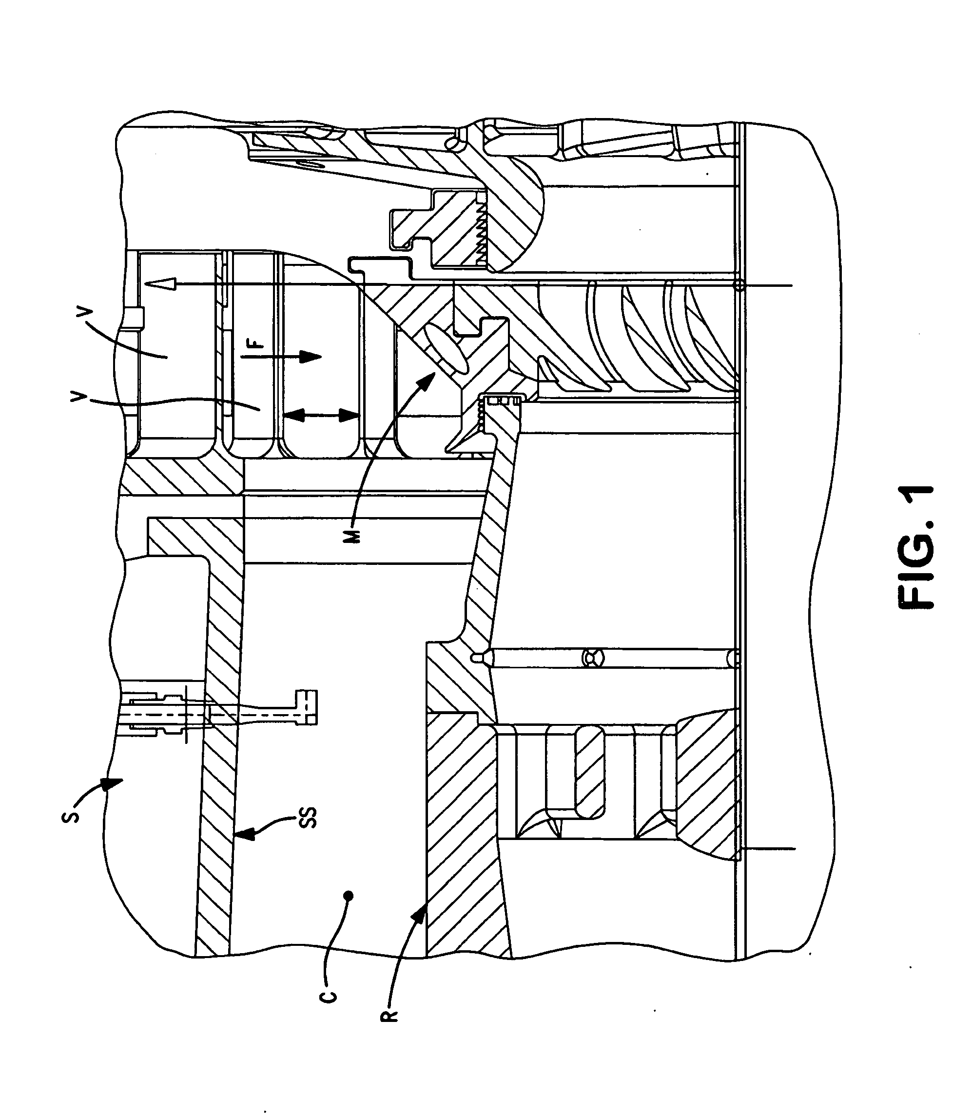
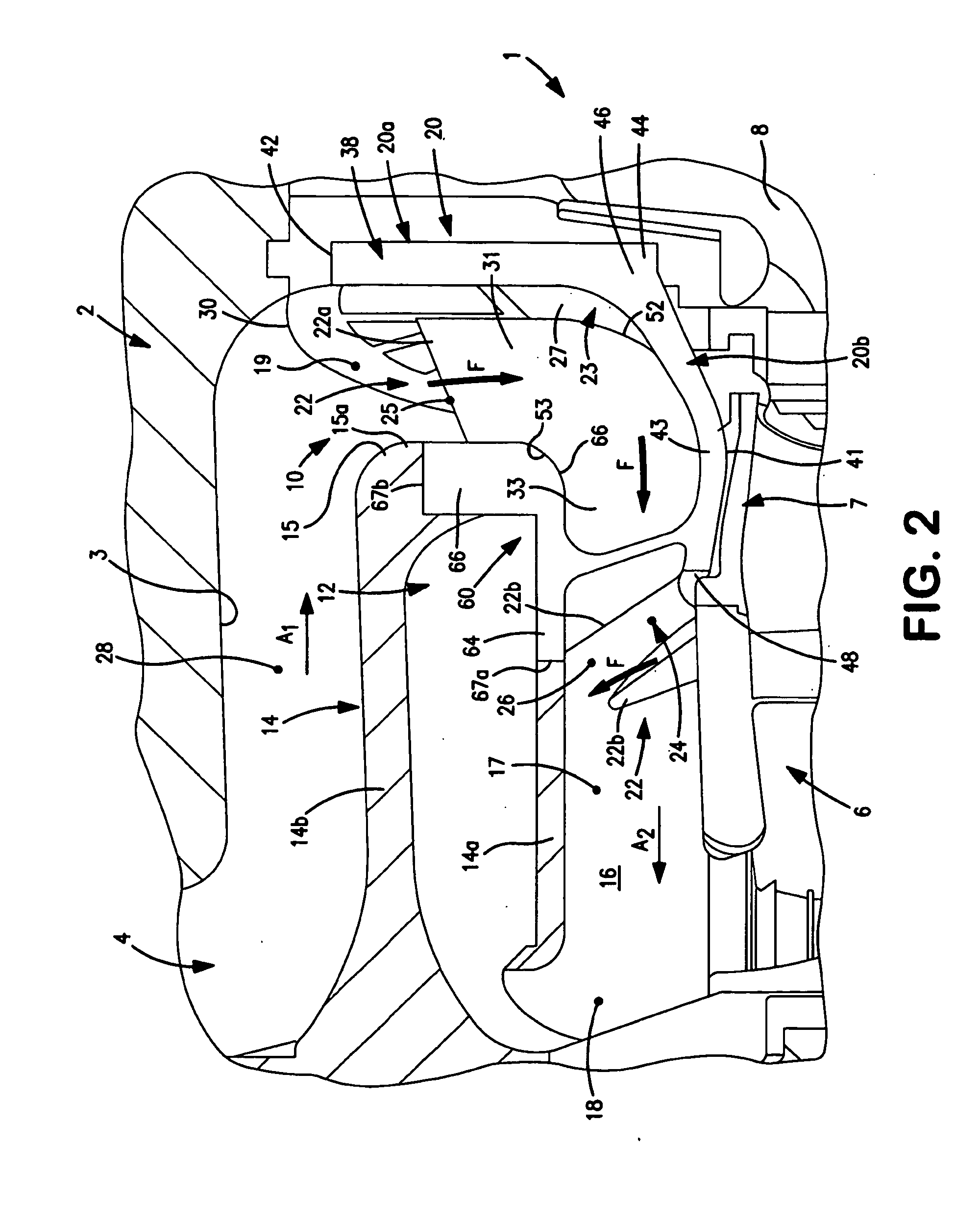
[0026]Referring now to the drawings in detail, wherein like numbers are used to indicate like elements ...


PUM

PropertyMeasurementUnit
angle ACaaaaaaaaaa
pressureaaaaaaaaaa
massaaaaaaaaaa

Abstract

A fluid deflector is for a fluid separator including a central axis and an enclosed wall having an open end and an inner circumferential separation surface extending about the axis to define an interior separation chamber. The fluid deflector includes a base disposeable proximal to the wall open end and having a central axis collinear with the separator axis. A plurality of vanes are connected with the base so as to be spaced circumferentially about the central axis. The vanes define a plurality of flow channels each bounded by a separate pair of adjacent vanes and having an inlet and an outlet. Each vane directs flow through a bounded channel generally radially inwardly from the channel inlet toward the channel outlet and generally circumferentially and radially outwardly from the channel outlet.

Description

[0001]The present invention relates to fluid machinery, and more particularly to combination separator and compressor devices.[0002]Centrifugal compressors are known and typically include one or more impellers mounted on a driven shaft and configured to pressurize gas drawn into a central inlet and to discharge the fluid radially outwardly through one or more outlets located at an outer circumferential perimeter thereof. In order to properly function, only gas should be directed into the compressor inlet, such that any liquids should be removed from a fluid stream prior to entry into the compressor. As such, compressors are often used in conjunction with a separator device to remove liquids from the fluid stream prior to entry into the compressor inlet.[0003]Referring to FIG. 1, one type of separator is a static separator S that uses swirler vanes V in conjunction with a separation surface SS bounding an interior separation chamber C. The swirler vanes V cause a fluid stream F to ge...

Claims


Application Information

Patent Timeline
Patent Type & Authority Applications(United States)
IPC IPC(8): F03B11/02B01D33/15
CPCF04D29/701F04D29/441
Inventor MAIER, WILLIAM C.CHOCHUA, GOCHA T.
Owner DRESSER RAND CO
Why Eureka
Try Eureka