

Vehicular air conditioning apparatus and air conditioning method
a technology of air conditioning apparatus and passenger compartment, which is applied in the direction of transportation and packaging, process and machine control, instruments, etc., can solve the problem of front seat passenger feeling uncomfortable, and achieve the effect of rear air conditioning zon
- Summary
- Abstract
- Description
- Claims
- Application Information
AI Technical Summary
Benefits of technology
Problems solved by technology
Method used
Image

Examples
first embodiment
[0023]A first embodiment will now be described with reference to FIGS. 1 to 7.
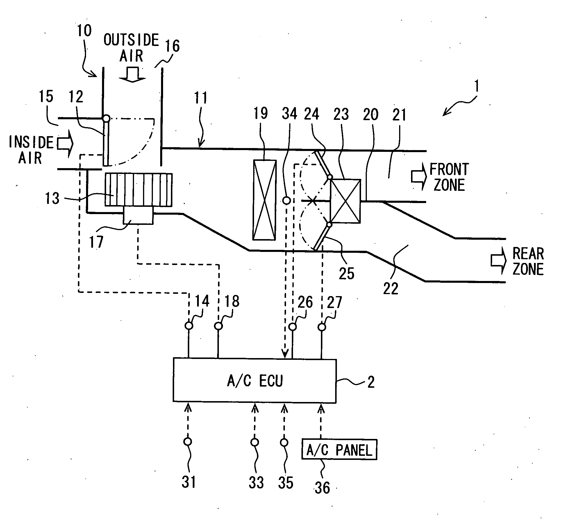
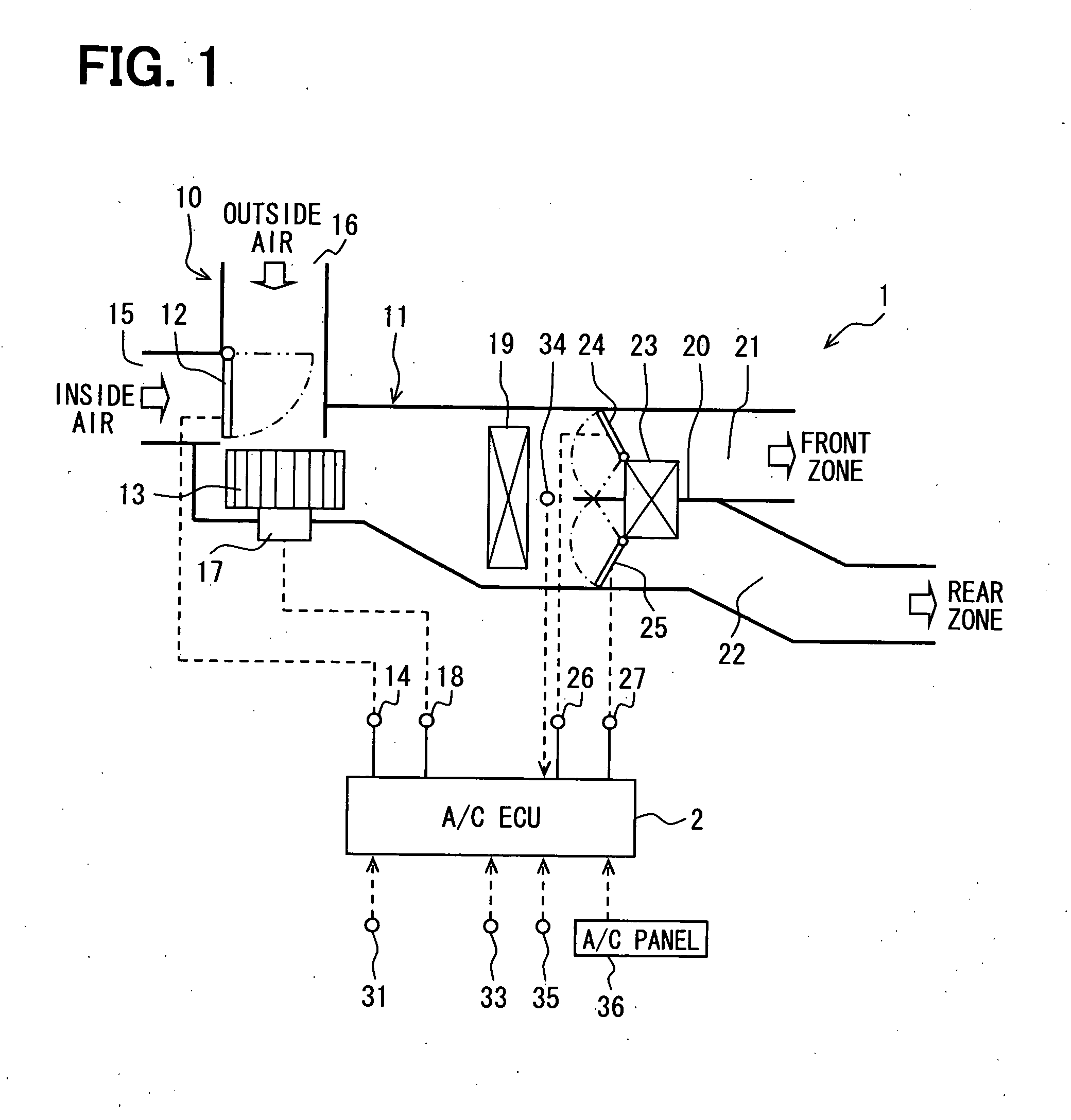
[0024]An air conditioning apparatus is configured for controlling a passenger compartment of a vehicle, which has an engine. In the present embodiment, the vehicular air conditioning apparatus is configured such that the temperature of air blown toward a front air conditioning zone (front seat zone) and the temperature of air blown toward a rear air conditioning zone (rear seat zone) are independently controlled.
[0025]Referring to FIG. 1, the air conditioning apparatus generally includes an air conditioning unit (hereinafter, simply referred to as the a / c unit) 1 and an air conditioner ECU (hereinafter, simply referred to as the a / c ECU) 2 for controlling electric actuators of the a / c unit 1. The a / c unit 1 generally includes a blower unit 10 and an air conditioning duct 11 as a ventilation system.
[0026]For example, the blower unit 10 and the duct 11 are mounted in a lower portion of an instrument panel in...
second embodiment
[0085]A second embodiment will be described with reference to FIGS. 8 and 9. In the present embodiment, the correction air volume level Vadi can be calculated using a gain correction term kVai obtained in accordance with the deviation between the front target temperature FrTAOi and the rear target temperature RrTAOi. FIG. 8 shows a flowchart illustrating a procedure for calculating the correction air volume level Vadi of the present embodiment, and FIG. 9 is a diagram for obtaining the gain correction term kVai.
[0086]Referring to FIG. 8, at S54a, the correction air volume level Vadi is calculated based on the following equation (8):
Vadi=kVai×(RrBLWdi−kFrBLWdi×FrBLWdi) (8)
[0087]That is, the correction air volume level Vadi is given by multiplying each of correction terms calculated at S51, S52, S53 by the gain correction term kVai. The gain correction term kVai is calculated in accordance with the deviation between the front target temperature FrTAOi and the rear target temperature...
third embodiment
[0095]A third embodiment will be described with reference to FIGS. 10, 11, and 12. In the first and second embodiments, the air conditioning apparatus exemplarily has a function of independently controlling the temperature of air to be blown into the front air conditioning zone and the temperature of air to be blown into the rear air conditioning zone. In the present embodiment, the air conditioning apparatus further has a function of conducting automatic and independent air conditioning controls for right and left areas of the front air conditioning zone and right and left areas of the rear air conditioning zone.
[0096]FIG. 10 is a diagram illustrating arrangements of the front air mix door 24 and the rear air mix door 25, each of which is divided into a right section and a left section. FIG. 11 is a flowchart illustrating a basic routine of an automatic air conditioning control executed by the a / c ECU 2 of the present embodiment. FIG. 12 is a diagram for determining a variable coef...
PUM
 Abstract
Description
Claims
Application Information