

Extreme Ultraviolet Light Source Device
- Summary
- Abstract
- Description
- Claims
- Application Information
AI Technical Summary
Benefits of technology
Problems solved by technology
Method used
Image

Examples
first embodiment
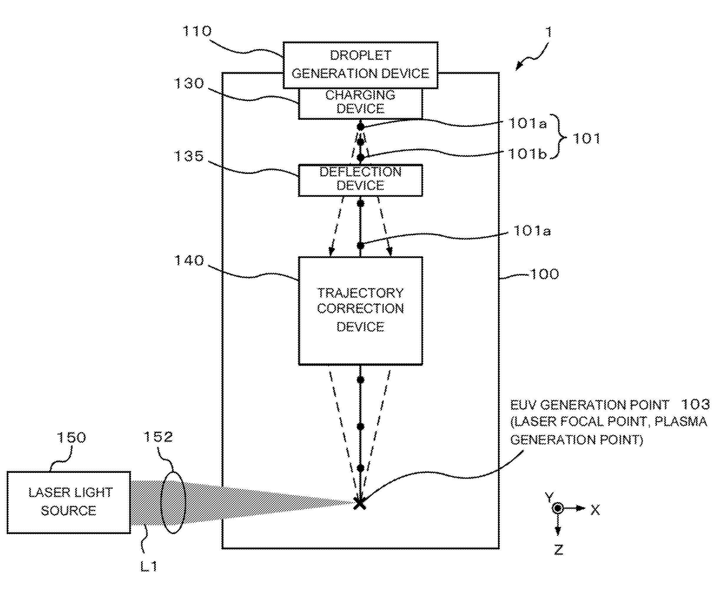
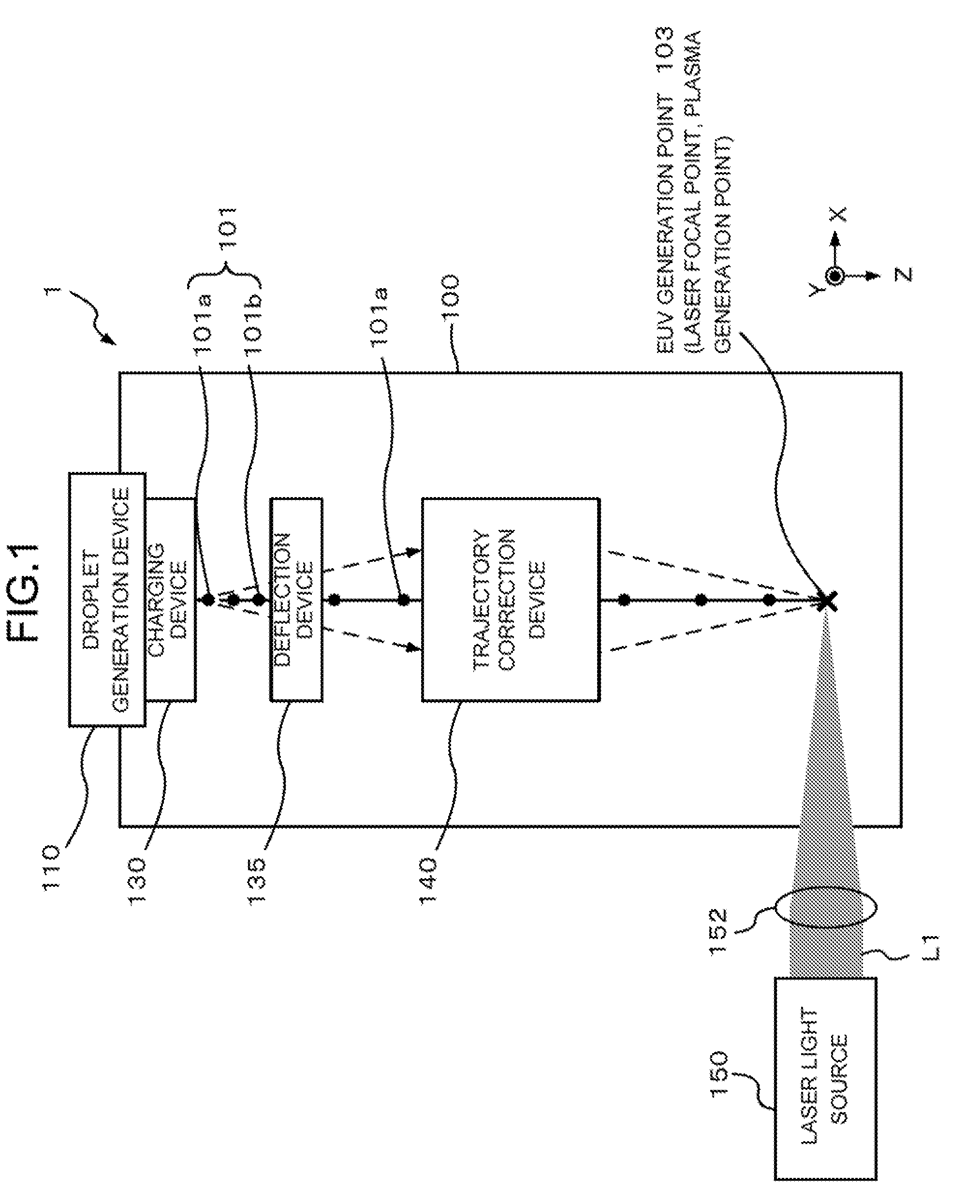
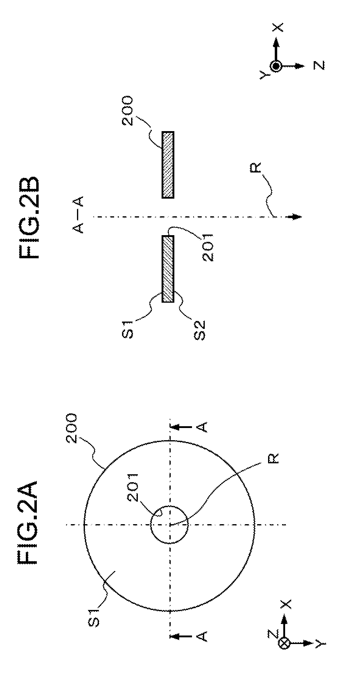
[0052]FIG. 2 illustrates an electrode comprised in the trajectory correction device 140. The electrode according to the embodiment has a single circular hole electrode 200. That is, the present embodiment is an example of a single electrode configuration. FIG. 2A is a plan-view diagram of the circular hole electrode 200, and FIG. 28 is a cross-sectional diagram of the circular hole electrode 200 along A-A. The circular hole electrode 200 is a plate-like electrode having a circular hole 201 positioned substantially in the center of a the electrode's circular form. The circular hole electrode 200 is perpendicular to an ideal trajectory R, and is disposed in such a manner that the center of the circular hole 201 coincides with the ideal trajectory R of the droplets 101a. Alternatively, a tubular electrode may be another example of a single-electrode configuration. In the case of a tubular electrode, as well, the electrode is disposed in such a manner that the center axis thereof coinci...
second embodiment
[0055]FIG. 4 illustrates an electrode comprised in the trajectory correction device 140.
[0056]FIG. 4A is a perspective-view diagram of a block electrode 220 according to the present embodiment. As illustrated in FIG. 4A, the block electrode 220 according to the present embodiment is a one-block block electrode comprising three circular hole electrodes 200A to 200C. The block electrode 220 comprises three coaxial circular hole electrodes 200A to 200C, disposed equidistantly parallel to each other. The center axis of the three circular hole electrodes 200A to 200C is disposed so as to coincide with the ideal trajectory R of the droplets 101a.
[0057]FIG. 4B is a cross-sectional diagram of the block electrode 220 taken along an X-Z plane that contains the ideal trajectory R. Herein, a circular hole electrode 200A (incidence side) and a circular hole electrode 200C (exit side) are kept at the same potential (for instance, ground potential), while a positive or negative potential is appli...
third embodiment
[0059]FIG. 5 illustrates an electrode employed in the trajectory correction device 140. The electrode in the present embodiment is a block electrode 310 comprising a quadrupole electrode of four cylindrical electrodes 300A to 300D. FIG. 5A is a plan-view diagram of the block electrode 310, and FIG. 5B is cross-sectional diagram of the block electrode 310 taken along B-B. The cylindrical electrodes 300A to 300D are parallel to each other, and are disposed equidistantly on a circle C1 having a predetermined radius, in such a manner that the center of the circle C1 coincides with the ideal trajectory R of the droplets 101a (shown in FIG. 1). The block electrode 310 of the present embodiment is a quadrupole electrode having four cylindrical electrodes, but may also be a multipole electrode having more than four cylindrical electrodes.
[0060]By adjusting the length of the cylindrical electrodes in the Z-axis direction (cylinder height), a stronger force can be exerted in a multipole elect...
PUM
| Property | Measurement | Unit |
|---|---|---|
| Force | aaaaa | aaaaa |
| Magnetic field | aaaaa | aaaaa |
| Electric field | aaaaa | aaaaa |
Abstract
Description
Claims
Application Information