
Brake force detecting device

Inactive Publication Date: 2008-04-03
HONDA MOTOR CO LTD +1
View PDF22 Cites 12 Cited by
  • Summary
  • Abstract
  • Description
  • Claims
  • Application Information

AI Technical Summary

Benefits of technology

[0008]It is therefore an object of the present invention to provide a brake force detecting device which can suppress the influence of a vertical force and a lateral force upon the strain in a sensor plate to thereby stabilize a detection output.
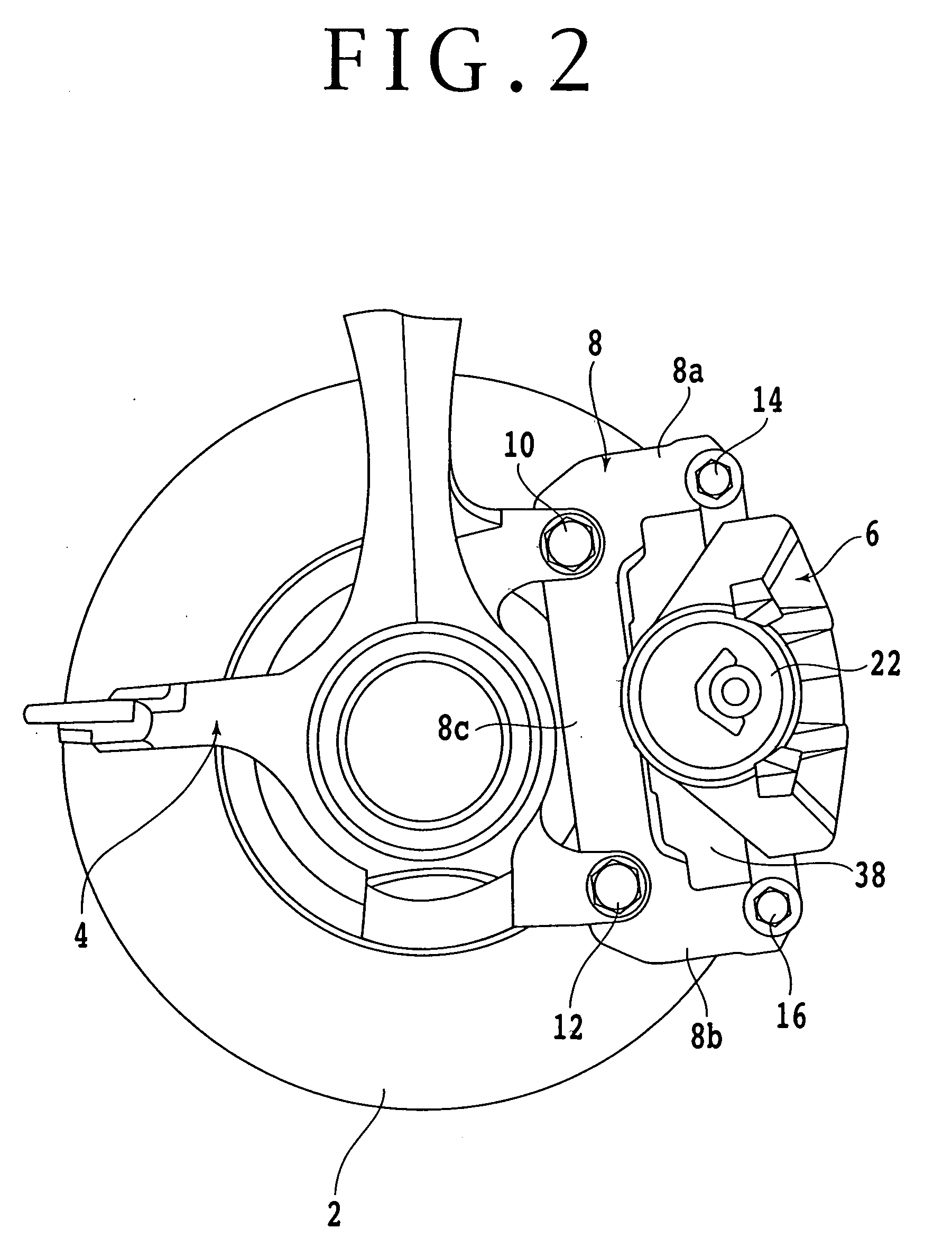
[0010]With this configuration, the sensor plate is fixed to the wheel support so that the straight line connecting the centers of the two bolts for fixing the caliper bracket to the wheel support is perpendicular to the straight line connecting the centers of the two bolts for fixing the sensor plate to the wheel support as viewed in side elevation. Accordingly, the sensor plate mainly undergoes a bending moment upon braking, and the sensor plate is deformed (strained) according to this bending moment. This strain in the sensor plate is detected by the strain detecting means, thereby allowing accurate detection of a brake force.

Problems solved by technology

According to the brake force measuring device described in Japanese Patent Laid-open No. 6-123665, the brake force measuring device has an H-shaped cross section, so that the distance between the caliper bracket and the knuckle in the axial direction of the brake disc is large, causing an increase in size of the measuring device.
Further, it is difficult to arrange a displacement detecting device between the two beams.
Accordingly, strain is generated both in a tensile direction and in a compressive direction, so that the zero point calibration for a sensor output is difficult, causing a problem on stabilization of a detection output.

Method used


Image

  • Brake force detecting device
  • Brake force detecting device
  • Brake force detecting device

Examples


Embodiment Construction

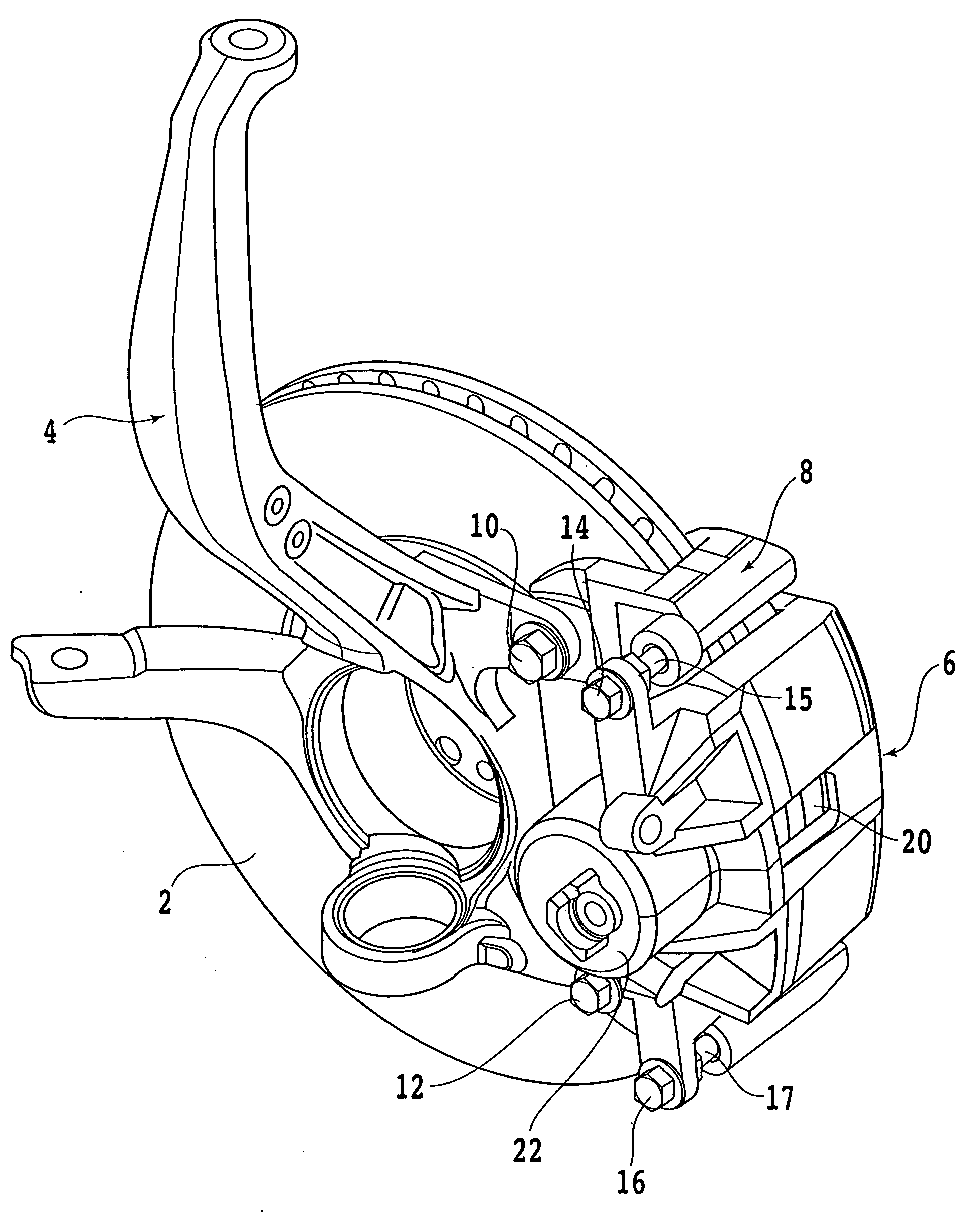
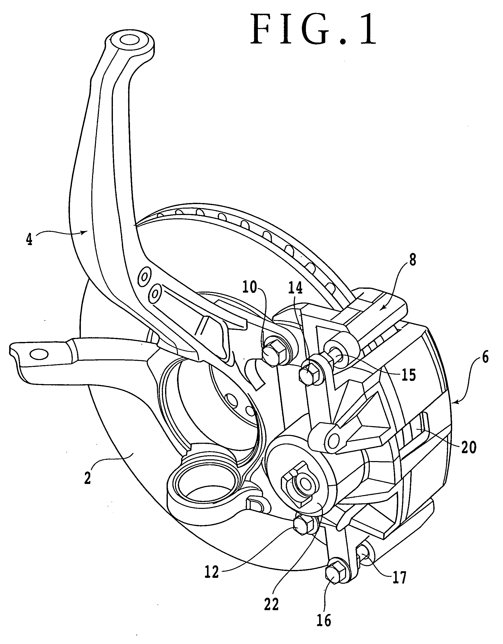
[0018]A preferred embodiment of the present invention will now be described in detail with reference to the drawings. FIG. 1 is a perspective view of a disc brake including a brake force detecting device according to a preferred embodiment of the present invention. FIG. 2 is a left side view of the disc brake shown in FIG. 1. As shown in FIGS. 1 and 2, a brake disc (disc rotor) 2 is fixed to a wheel (not shown), so that the brake disc 2 is rotated with the wheel. Reference numeral 4 denotes a knuckle (wheel support) for rotatably supporting the wheel. The knuckle 4 is connected through a suspension (not shown) to a vehicle body (not shown).

[0019]Reference numeral 8 denotes a caliper bracket, which is mounted to the knuckle 4 by two bolts 10 and 12. The caliper bracket 8 supports a pair of friction pads 18 and 20 at two opposite positions in the rotational direction (circumferential direction) of the brake disc 2, i.e., at a disc inlet position and a disc outlet position in the rotat...


PUM


Abstract

A brake force detecting device having a sensor plate fixed to a knuckle. A straight line connecting the centers of two bolts for fixing a caliper bracket to the knuckle is perpendicular to a straight line connecting the centers of two bolts for fixing the sensor plate to the knuckle as viewed in side elevation. A strain gauge is attached to the sensor plate.

Description

BACKGROUND OF THE INVENTION[0001]1. Field of the Invention[0002]The present invention relates to a brake force detecting device for detecting a brake force produced by a disc brake.[0003]2. Description of the Related Art[0004]In the case of performing braking control for a vehicle, a brake force is one of the important items of information. For example, if a brake force actually applied during braking can be detected, the condition of a road surface can be easily estimated. If the condition of a road surface can be estimated, ABS control (antiskid brake system control) can be performed more precisely, and the vehicle can therefore be braked to a halt safely in a short distance. Further, if a brake force applied to each wheel can be detected in braking during turning of the vehicle or during running on a slippery road surface having a low coefficient of friction (μ), the brake forces for all the wheels can be individually controlled to thereby allow safer running control of the vehic...

Claims


Application Information

Patent Timeline
IPC IPC(8): F16D66/00
CPCF16D55/00F16D2066/005F16D2055/0008F16D66/00
Inventor HORIUCHI, TAKEHIROINAGAKI, HIROMIOHMORI, TAKAYUKIYOSHIUCHI, SHIGEHIROICHINOMIYA, NORITAKA
Owner HONDA MOTOR CO LTD
Learn More