Unlock instant, AI-driven research and patent intelligence for your innovation.

Display apparatus and display control method

Active Publication Date: 2010-02-04
CANON KK
View PDF5 Cites 2 Cited by
  • Summary
  • Abstract
  • Description
  • Claims
  • Application Information

AI Technical Summary

Benefits of technology

[0032]a control step of controlling a read/write access of an image with respect to the memory based on the rendering command information, in accordance with the speeds decided in the decision step.
[0033]According to the fourth aspect of the present invention, a display control method f

Problems solved by technology

However, in order to smoothly composite high-definition movie data and graphics data, high-speed memory transfer is required, resulting in an expensive system.
In such cases, the qualities of movie and graphics data have to be adaptively controlled, but the aforementioned related arts cannot solve these problems.
For example, the techniques disclosed in patent references 1 and 2 execute movie rendering control to reduce the memory bandwidth to be used, but they cannot execute graphics rendering control.
Also, these techniques cannot adaptively control a band used to render movie data and that used to render graphics data as the situation demands.

Method used


Image

  • Display apparatus and display control method
  • Display apparatus and display control method
  • Display apparatus and display control method

Examples


first embodiment

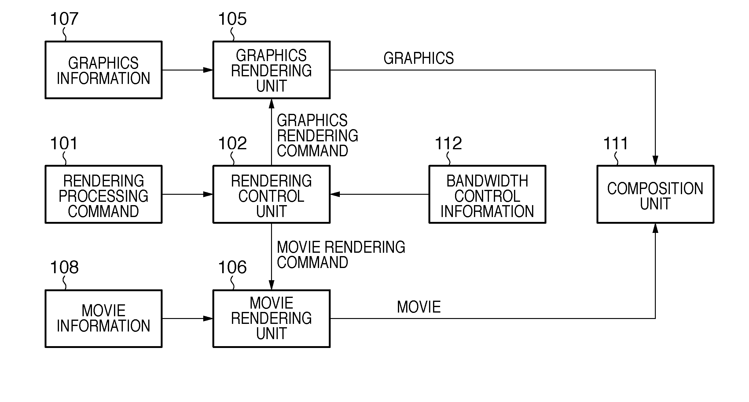
[0055]FIG. 1 is a block diagram showing an example of the functional arrangement of a display apparatus according to this embodiment. The display apparatus according to this embodiment includes a graphics rendering unit 105, movie rendering unit 106, rendering control unit 102, and composition unit 111.

[0056]The graphics rendering unit 105 receives graphics information 107 as graphics data. The graphics information 107 includes, for example, data of a tone volume indication object, channel indication object, and the like. These objects are to be composited on movie data to be described later. The graphics rendering unit 105 renders graphics data using this graphics information 107 under the control of the rendering control unit 102. This rendering processing is executed on a memory (not shown) included in the display apparatus.

[0057]The movie rendering unit 106 receives movie information 108 as movie data. The movie information 108 includes, for example, image data, number informati...

second embodiment

[0137]In this embodiment, the currently used read / write speeds are monitored, and the graphics and movie rendering processes are controlled in accordance with the monitored read / write speeds without using the bandwidth control information 112. Differences from the first embodiment will be described below.

[0138]FIG. 7 is a block diagram showing an example of the functional arrangement of a display apparatus according to this embodiment. Note that the same reference numerals in FIG. 7 denote the same parts as in FIG. 1, and a repetitive description thereof will be avoided.

[0139]A bandwidth monitoring unit 701 monitors a graphics read / write speed and movie read / write speed in real time by monitoring read / write request signals, addresses, and data issued on a memory bus, and notifies the rendering control unit 102 of the monitoring result as bandwidth information.

[0140]FIG. 8 is a flowchart of processing executed when the display apparatus according to this embodiment composites and dis...

third embodiment

[0145]In this embodiment, a graphics read / write speed and movie read / write speed at the next timing are predicted from the current graphics read / write speed and current movie read / write speed without using the bandwidth control information 112. Then, the graphics and movie rendering processes are controlled in accordance with the predicted read / write speeds.

[0146]FIG. 10 is a block diagram showing an example of the functional arrangement of a display apparatus according to this embodiment. Note that the same reference numerals in FIG. 10 denote the same parts as in FIG. 1, and a repetitive description thereof will be avoided.

[0147]A bandwidth prediction unit 1001 predicts graphics and movie read / write speeds based on the resolution, number of colors, and frame rate of graphics data which is currently displayed, and the number of movies which are currently displayed, and notifies the rendering control unit 102 of the prediction result as bandwidth prediction information 1002. The ban...


PUM


Abstract

A rendering control unit determines movie and graphic display modes with reference to a rendering processing command, and acquires maximum speed information indicating the maximum value of a read / write speed allowed for a memory. The rendering control unit decides a speed to be distributed to a read / write speed of the movie data and a speed to be distributed to a read / write speed of the graphic data with respect to the memory, of a maximum speed indicated by the maximum speed information, based on the determination result. The rendering control unit controls a read / write access of an image with respect to the memory based on the rendering processing command, in accordance with the decided speeds.

Description

BACKGROUND OF THE INVENTION[0001]1. Field of the Invention[0002]The present invention relates to a display technique which can composite and display movie and graphic data.[0003]2. Description of the Related Art[0004]Nowadays, the broadcasting scene is making a shift from analog broadcasting to digital broadcasting to provide multi-channel broadcasts and high-definition contents. Display apparatuses which display such broadcast contents increasingly have larger screens and higher definitions.[0005]Also, receivers are changing from those which merely display broadcast video images one-sidedly to those which include a mechanism that allows users to enjoy interactive services by data broadcasting and the like. As a result, the receivers are required to composite graphics data as in general personal computers.[0006]As described above, along with the advent of digital broadcasting, and large-screen, high-definition display apparatuses, a display mode called “multi-window display” that si...

Claims


Application Information

Patent Timeline
IPC IPC(8): H04N5/445G06F3/14G06F3/153G09G5/00G09G5/36G09G5/377H04N5/66
CPCG09G5/14G09G5/393G09G2340/0407G09G2340/0435G09G2340/125H04N21/8146H04N5/44504H04N5/44508H04N5/265H04N21/431G09G2350/00H04N21/434
Inventor SANO, AKIRANAGASHIMA, TAKAYUKI
Owner CANON KK