
Intraocular Lens System

a technology of intraocular lens and lens plate, which is applied in the field of intraocular lens, can solve the problems of non-optical components and inability to correct refractive errors, and achieve the effect of reducing or eliminating pco

Inactive Publication Date: 2010-02-04
ZHANG XIAOXIAO +1
View PDF7 Cites 5 Cited by
  • Summary
  • Abstract
  • Description
  • Claims
  • Application Information

AI Technical Summary

Benefits of technology

Enables safe, biocompatible, and adjustable IOLs that can be implanted through small incisions, reducing the incidence of PCO and providing improved vision correction with reduced need for additional corrective measures like spectacles or contact lenses.

Problems solved by technology

The first component is a non-optical component and does not correct for any refractive errors.

Method used


Image

  • Intraocular Lens System
  • Intraocular Lens System
  • Intraocular Lens System

Examples


second embodiment

[0033]As best seen in FIG. 10, in the present invention, first or base component 12′ has an inner rim or lip 150 that is slightly elliptical, oval, out-of-round or non-circular in shape having a short axis 100 and a long axis 102. This slightly oval or otherwise out of round shape will vary the amount of compression on haptics 24 of second component 14. Rotation of second component 14 so that haptics 14 are be aligned along short axis 100 will cause haptics 14 to more compressed than rotation of second component 14 so that haptics 14 are be aligned along long axis 102, thereby changing the position of 15 along optical axis 28 and correspondingly varying the effective refractive power of lens system 10 implanted in an eye.

third embodiment

[0034]As best seen in FIG. 11, in the present invention, inner rim or lip 200 of first or base component 12″ contains a plurality of cam ridges 201, 202 and 203 or varying step height. Rotation of second component 14 within base component 12″ causes haptics 24 to ride along on ridges 201, 202 or 203, thereby varying the location of optic 15 along optical axis 28 and correspondingly changing the effective refractive power of lens system 10 implanted in an eye.


PUM


Abstract

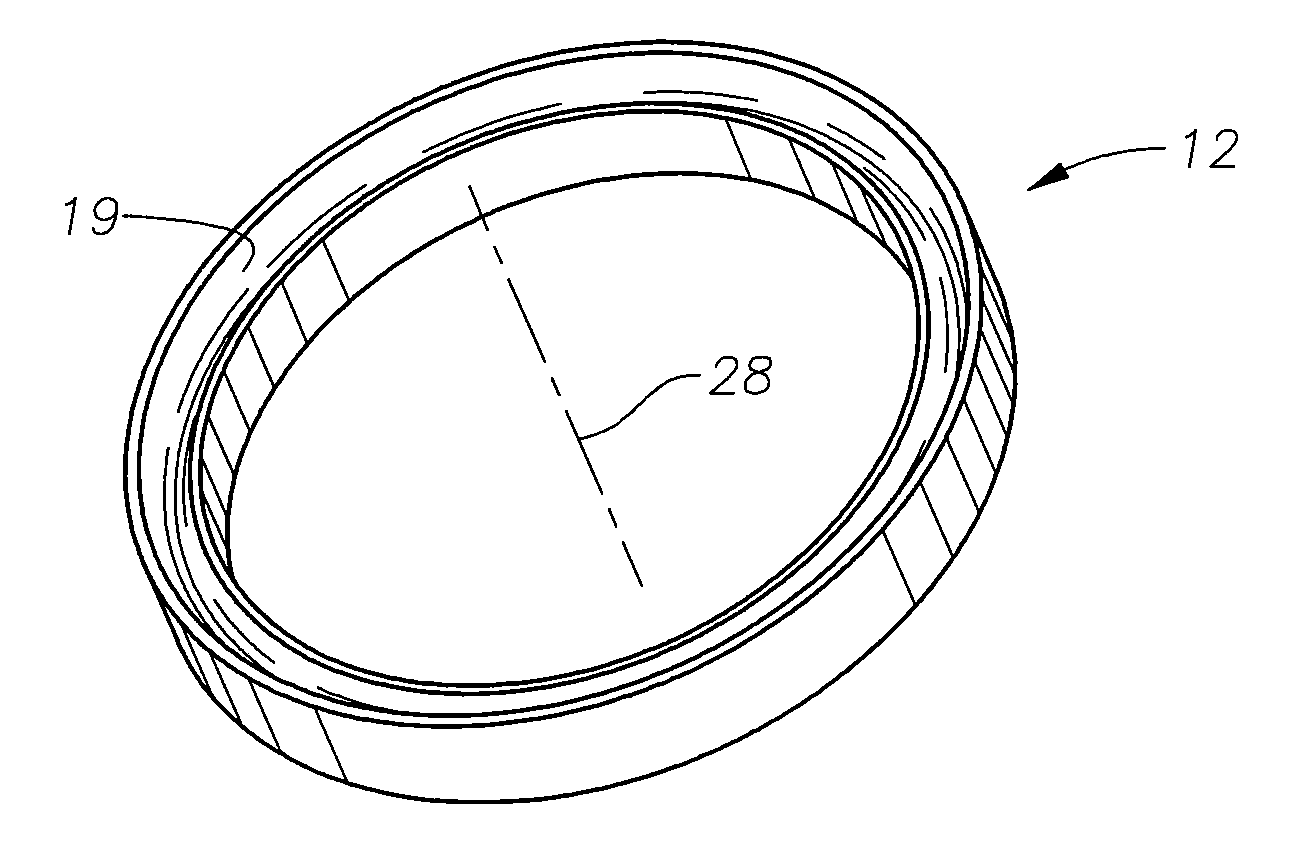
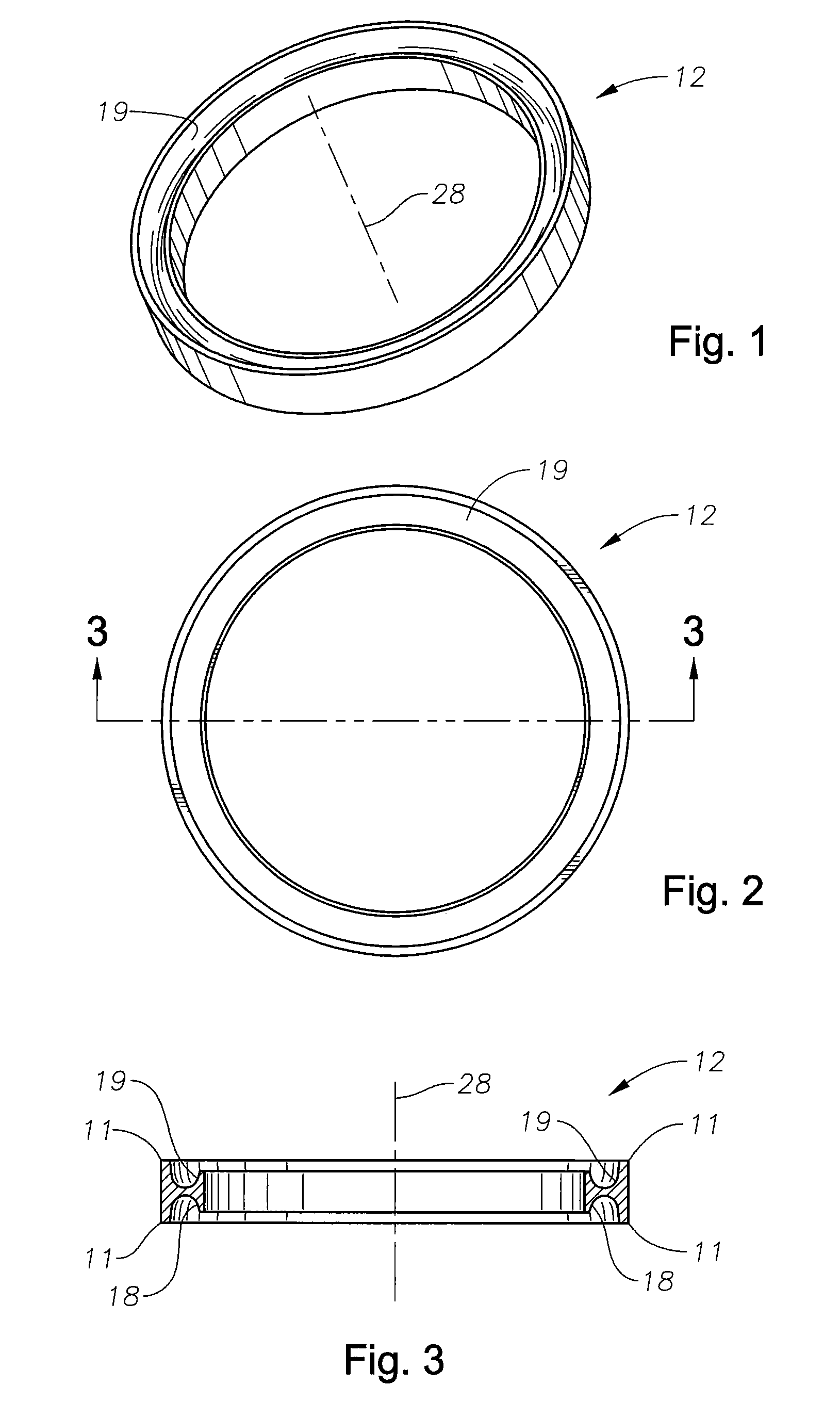
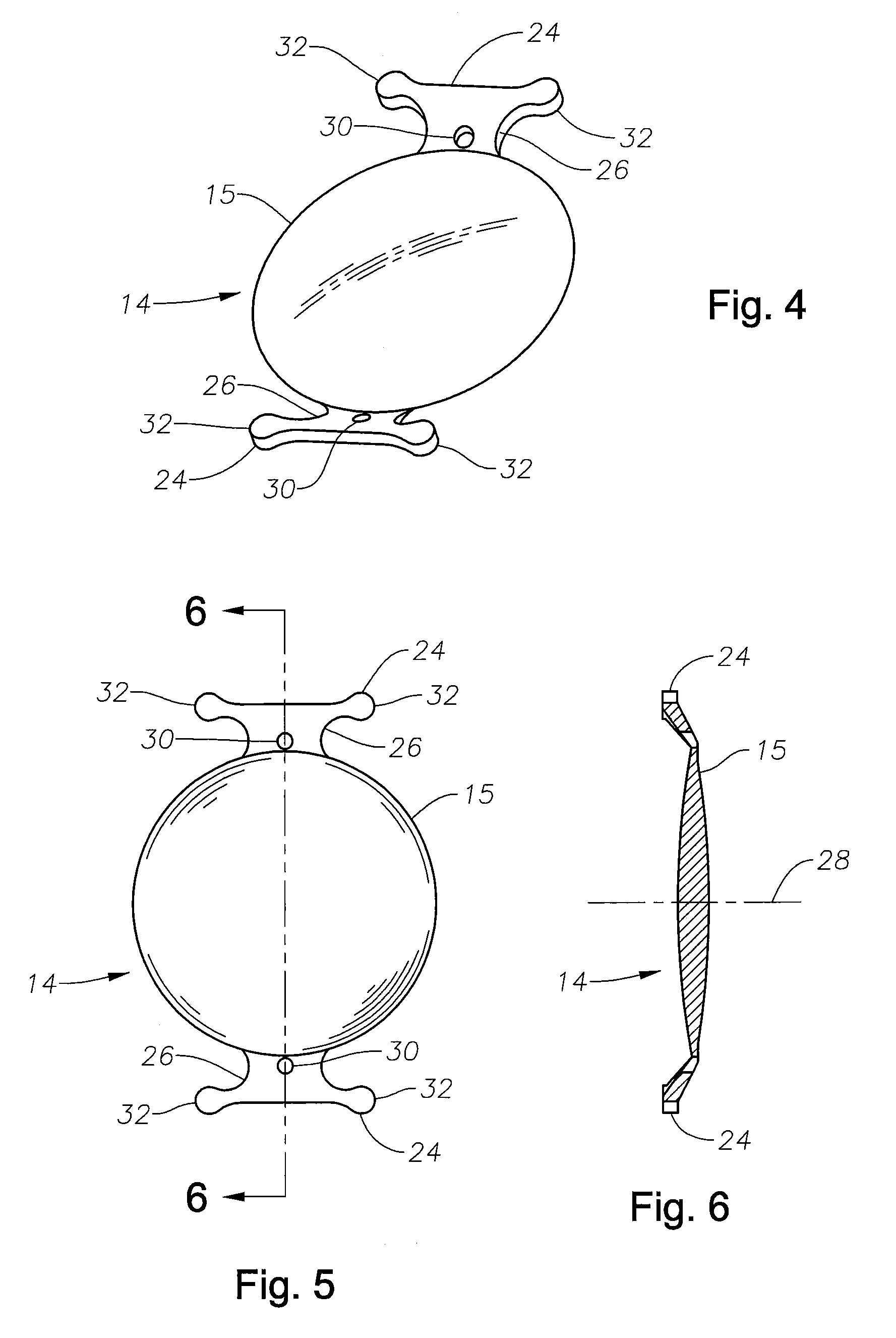
A two or three component lens system. The first component is a ring-like supporting component that is implanted in the capsular bag following cataract surgery. The first component is a non-optical component and does not correct for any refractive errors. The first component may contain features to help reduce or eliminate PCO. The second component is an optical component that may contain all of the corrective optical power of the lens system. The second component has a pair of tabs for locking the second component within the first component. The first component includes a feature that allows the surgeon to change the position of the second component along the optical axis of the lens system. The third component is optional and is similar to second component and contains some optical power to correct for any residual optical error not corrected by the second component. The second and third components may also be implanted so as to move relative to one another, thereby providing some accommodation.

Description

[0001]This application claims priority from, and is a continuation of U.S. patent application Ser. No. 11 / 178,758 filed on Jul. 11, 2005.BACKGROUND OF THE INVENTION [0002]This invention relates generally to the field of intraocular lenses (IOL) and, more particularly, to multi-lens, micro-incision IOLs.[0003]The human eye in its simplest terms functions to provide vision by transmitting light through a clear outer portion called the cornea, and focusing the image by way of a crystalline lens onto a retina. The quality of the focused image depends on many factors including the size and shape of the eye, and the transparency of the cornea and the lens.[0004]When age or disease causes the lens to become less transparent, vision deteriorates because of the diminished light which can be transmitted to the retina. This deficiency in the lens of the eye is medically known as a cataract. An accepted treatment for this condition is surgical removal of the lens and replacement of the lens fun...

Claims


Application Information

Patent Timeline
Patent Type & Authority Applications(United States)
IPC IPC(8): A61F2/16
CPCA61F2/1629A61F2/1694A61F2/1648
Inventor ZHANG, XIAOXIAOSOYE, PAUL
Owner ZHANG XIAOXIAO
Learn More