
Row-modulation gray-level LCD device and method thereof

Inactive Publication Date: 2010-02-11
POWERTIP TECH
View PDF1 Cites 0 Cited by
  • Summary
  • Abstract
  • Description
  • Claims
  • Application Information

AI Technical Summary

Benefits of technology

[0009]The single-level driver sequentially generates a plurality of original common voltage signals. At least two original common voltage signals input to the common electrodes in a time-division mode to generate a new common voltage signal. The voltage d

Problems solved by technology

In other words, the output control of the segment circuit needs a special design, which increases the complexity and cost of the circuit.

Method used


Image

  • Row-modulation gray-level LCD device and method thereof
  • Row-modulation gray-level LCD device and method thereof
  • Row-modulation gray-level LCD device and method thereof

Examples


Embodiment Construction

[0016]Below, the technical contents of the present invention are described in detail in cooperation with the drawings.

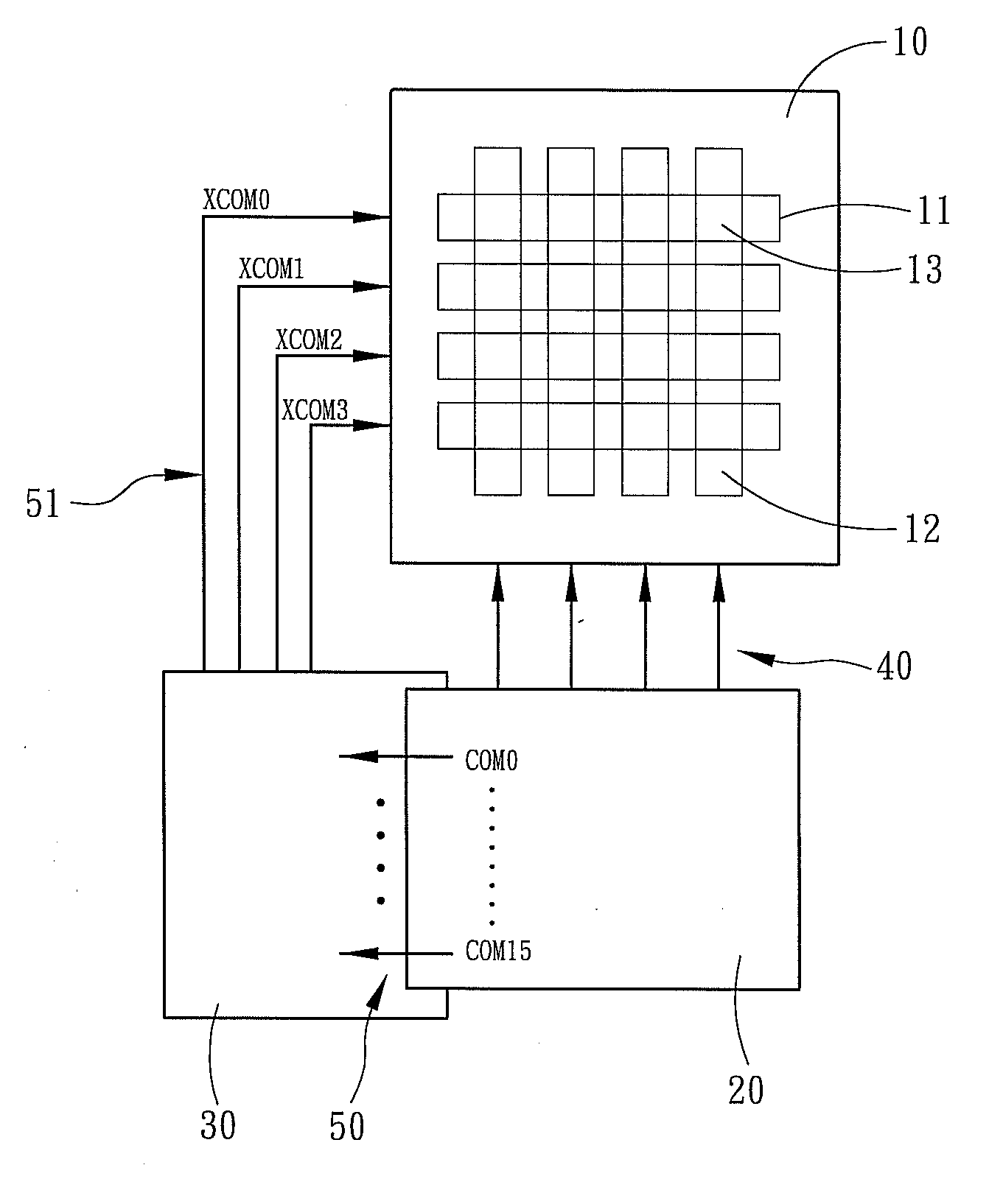
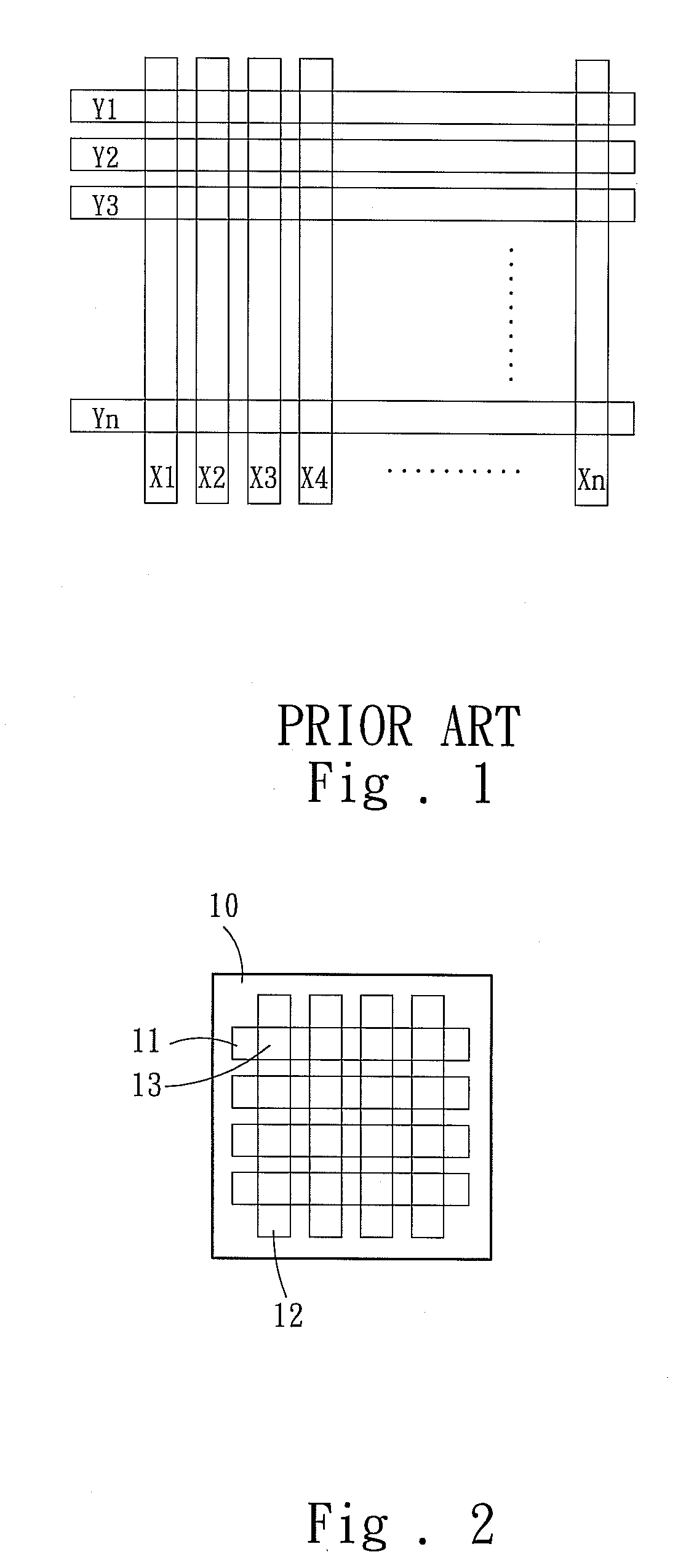
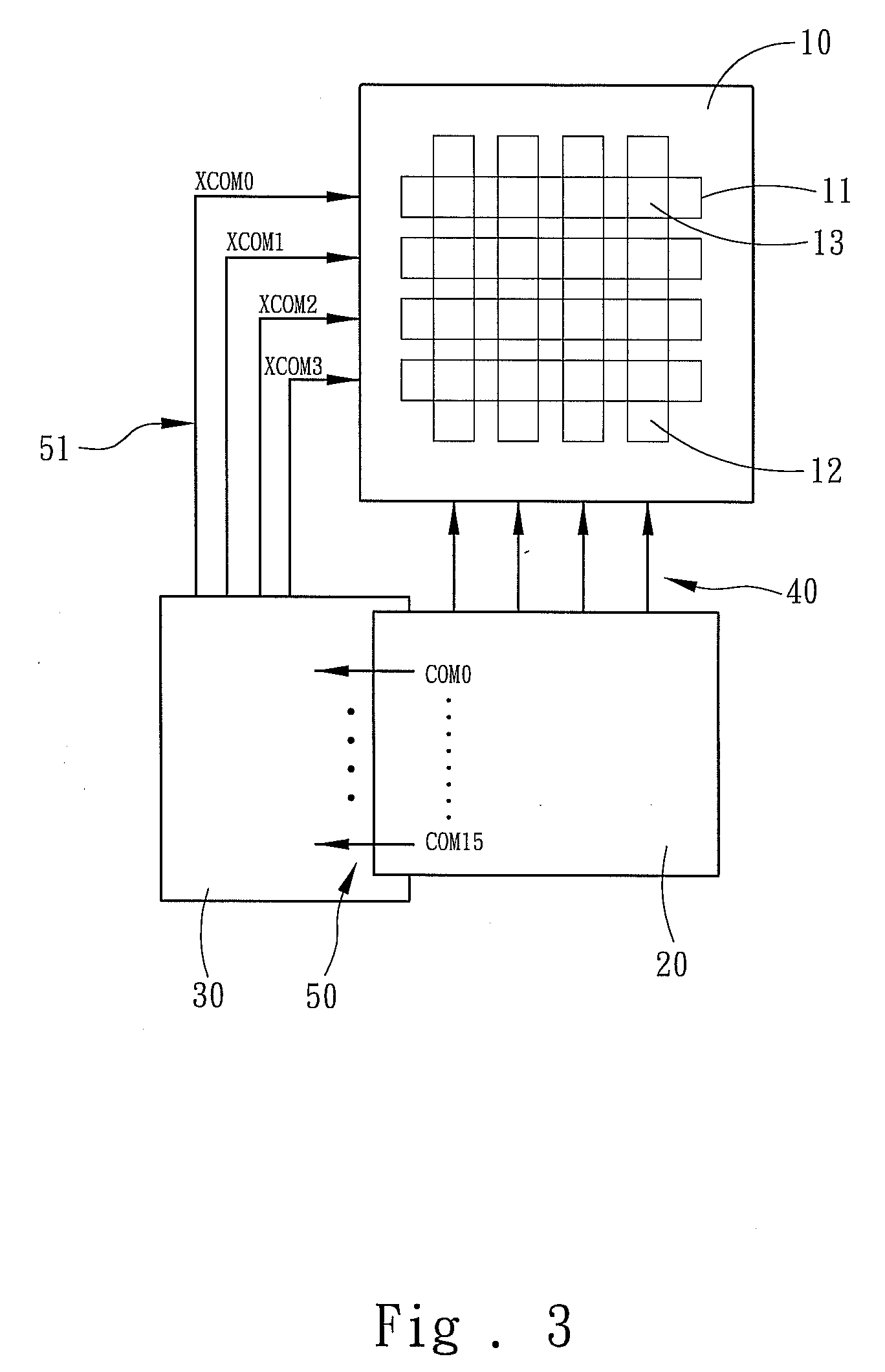
[0017]Refer to FIG. 2 and FIG. 3. The system of the present invention comprises a monochromatic LCD panel 10, a single-level driver 20 and a row-modulation device 30. The monochromatic LCD panel 10 has a plurality of common electrodes 11 and a plurality of segment electrodes 12; the common electrodes 11 and the segment electrodes 12 intersect vertically and are respectively arranged on an upper layer and a lower layer. Thus, the monochromatic LCD panel 10 has a plurality of monochromatic pixels 13 corresponding to the intersections of the common electrodes 11 and the segment electrodes 12. The monochromatic LCD panel 10 shown in the drawings is a LCD panel having a resolution of 4×4, but the present invention is not limited thereto.

[0018]Refer to FIG. 4 also. The single-level driver 20 sequentially generates a plurality of original common voltage signals 21 and a plu...


PUM


Abstract

A row (common electrode)-modulation gray-level LCD device and a method thereof, which use a row-modulation device to input at least two sequentially generated original common voltage signals to the common electrode of the same row, whereby the sequentially generated original common voltage signals cooperate with the segment voltage signals to generate voltage differences in the common electrode and turn on or turn off the same monochromatic pixel in a time-division mode. The accumulated effect of the time-division turn-on and turn-off states enables the same monochromatic pixel to present gray-pixel.

Description

FIELD OF THE INVENTION[0001]The present invention relates to an LCD device and a method thereof, particularly to an LCD device and a method thereof, whereby a single-level drive monochromatic LCD panel can have gray levels.BACKGROUND OF THE INVENTION[0002]Refer to FIG. 1, a diagram schematically showing the electrodes of an LCD panel. Electrodes X1-Xn and Electrodes Y1-Yn are arranged crosswise to form a matrix, and each intersection point is a pixel on the panel. A pixel lightens or darkens according to the voltage difference applied thereon. The gray level which is shown from the LCD device is usually realized with a FRM (Frame Rate Modulation) or PWM (Pulse Width Modulation) technology.[0003]In the FRM technology, the gray level is determined by the ratio of turn-on cycles and turn-off cycles per second. Thus, the display time of each pixel has to increase, and light has to accumulate to a sufficient amount during the interval of vision persistence. Besides, the frequency of ligh...

Claims


Application Information

Patent Timeline
IPC IPC(8): G09G3/36
CPCG09G3/2014G09G3/3681G09G3/3622G09G3/2025
Inventor WANG, SHYH-YUEHJEAN, CHUEN-TZAYCHEN, CHIA-HUIHUANG, CHIU-YUANCHEN, YEN-LIANGTANG, WEI-JENHSU, CHIEN-CHIH
Owner POWERTIP TECH
Learn More