
Embedding hidden auxiliary code signals in media

a technology of auxiliary codes and signals, applied in the field of embedded robust identification codes, can solve the problems of confusion and corruption of original work, loss of revenues for the owners of such materials, and no simple means of tracing the path to the original purchaser of the material

Inactive Publication Date: 2006-02-21
DIGIMARC CORP
View PDF404 Cites 127 Cited by
  • Summary
  • Abstract
  • Description
  • Claims
  • Application Information

AI Technical Summary

Benefits of technology

[0013]What is needed is a reliable and efficient method for performing a positive identification between a copy of an original signal and the original. This method should not only be able to perform positive identification, it should also be able to relate version identification of sold copies in order to better pinpoint the point of sale. The method should not compromise the innate quality of material which is being sold, as does the placement of localized logos on images. The method should be robust so that an identification can be made even after multiple copies have been made and / or compression and decompression of the signal has taken place. The identification method should be largely uneraseable or “uncrackable.” The method should be capable of working even on fractional pieces of the original signal, such as a 10 second “riff” of an audio signal or the “clipped and pasted” sub-section of an original image.
[0014]The existence of such a method would have profound consequences on audio and image piracy in that it could (a) cost effectively monitor for unauthorized uses of material and perform “quick checks”; (b) become a deterrent to unauthorized uses when the method is known to be in use and the consequences well publicized; and (c) provide unequivocal proof of identity, similar to fingerprint identification, in litigation, with potentially more reliability than that of fingerprinting.
[0016]One embodiment uses identification signals which are global (holographic) and which mimic natural noise sources. This approach allows the maximization of identification signal energy as opposed to merely having it present ‘somewhere in the original material.’ This allows it to be much more robust in the face of thousands of real world degradation processes and material transformations such as cutting and cropping of imagery.
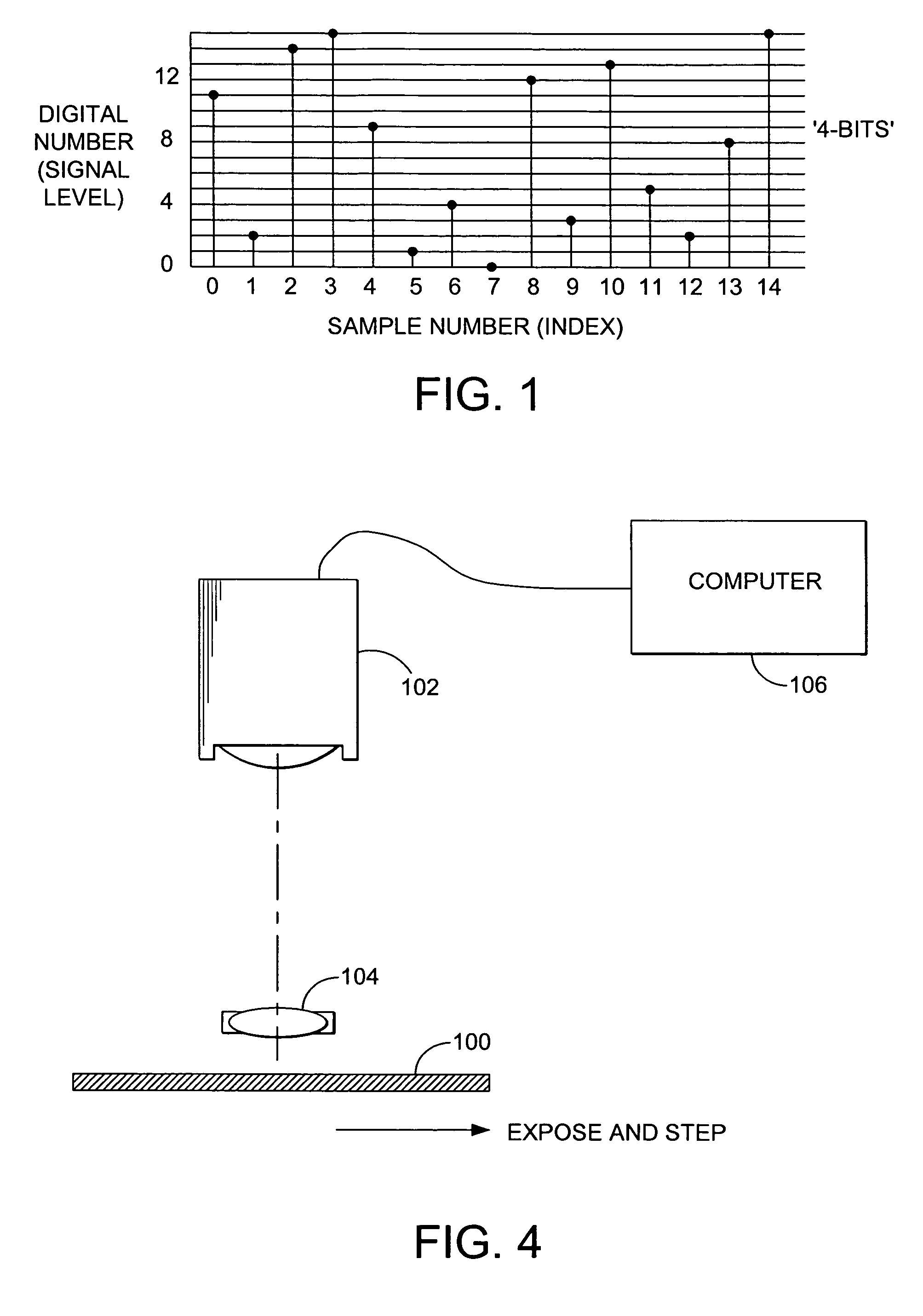
[0018]FIG. 1 is a simple and classic depiction of a one dimensional digital signal which is discretized in both axes.
[0056]So with these two values of X and Y, we now have constructed our first versions of a distributable copy of the original. Other versions will merely create a new composite signal and possibly change the X slightly if deemed necessary. We now lock up the original digital image along with the 32-bit identification word for each version, and the 32 independent random 4-bit images, waiting for our first case of a suspected piracy of our original. Storage wise, this is about 14 Megabytes for the original image and 32*0.5 bytes*16 million=˜256 Megabytes for the random individual encoded images. This is quite acceptable for a single valuable image. Some storage economy can be gained by simple lossless compression.Finding a Suspected Piracy of Our Image
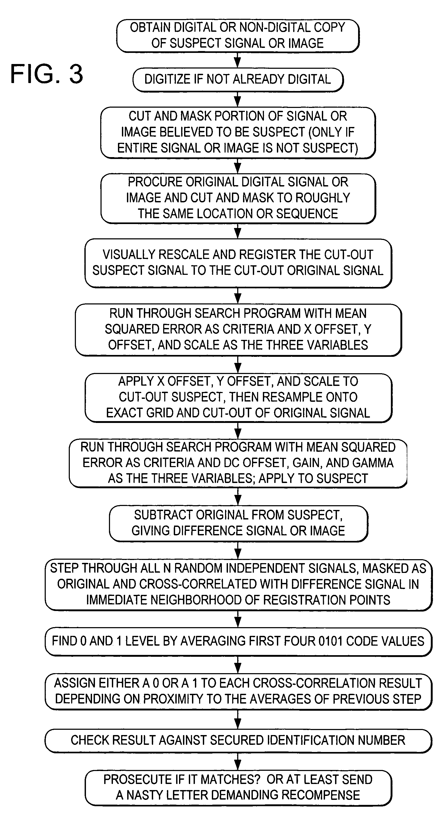
[0059]We now procure the original digital image from our secured place along with the 32-bit identification word and the 32 individual embedded images. We place the original digital image onto our computer screen using standard image manipulation software, and we roughly cut along the same borders as our masked area of the suspect image, masking this image at the same time in roughly the same manner. The word ‘roughly’ is used since an exact cutting is not needed, it merely aids the identification statistics to get it reasonably close.

Problems solved by technology

Since time immemorial, unauthorized use and outright piracy of audio and visual source material has caused lost revenues to the owners of such material, and has been a source of confusion and corruption of original work.
Furthermore, there is no simple means of tracing a path to an original purchaser of the material, something which can be valuable in tracing where a possible “leak” of the material first occurred.
This technique, however, requires that both the original and later descrambled signals never leave closed and controlled networks, lest they be intercepted and recorded.
Furthermore, this arrangement is of little use in the broad field of mass marketing audio and visual material, where even a few dollars extra cost causes a major reduction in market, and where the signal must eventually be descrambled to be perceived and thus can be easily recorded.
But in general, this is a highly inefficient form of embedding identification information for a variety of reasons: (a) the whole of the source material is not used; (b) deterministic patterns have a higher likelihood of being discovered and removed by a would-be infringer; and (c) the signals are not generally ‘holographic’ in that identifications may be difficult to make given only sections of the whole.

Method used


Image

  • Embedding hidden auxiliary code signals in media
  • Embedding hidden auxiliary code signals in media
  • Embedding hidden auxiliary code signals in media

Examples


specific example

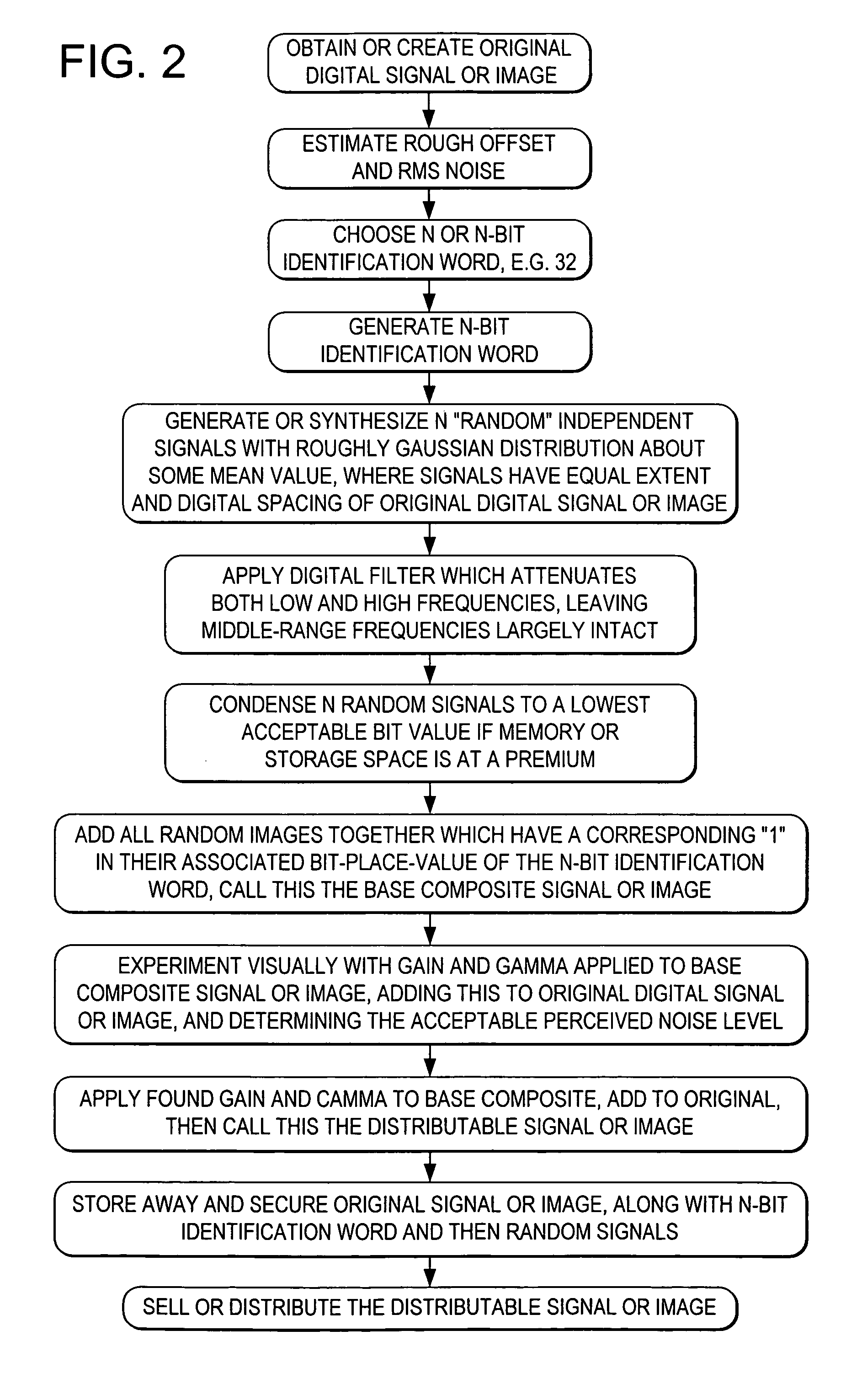
[0044]Imagine that we have taken a valuable picture of two heads of state at a cocktail party, pictures which are sure to earn some reasonable fee in the commercial market. We desire to sell this picture and ensure that it is not used in an unauthorized or uncompensated manner. This and the following steps are summarized in FIG. 2.

[0045]Assume the picture is transformed into a positive color print. We first scan this into a digitized form via a normal high quality black and white scanner with a typical photometric spectral response curve. (It is possible to get better ultimate signal to noise ratios by scanning in each of the three primary colors of the color image, but this nuance is not central to describing the core process.)

[0046]Let us assume that the scanned image now becomes a 4000 by 4000 pixel monochrome digital image with a grey scale accuracy defined by 12-bit grey values or 4096 allowed levels. We will call this the “original digital image” realizing that this is the sam...


PUM

PropertyMeasurementUnit
polarityaaaaaaaaaa
perceptibility thresholdaaaaaaaaaa
frequencyaaaaaaaaaa

Abstract

Methods for embedding and reading auxiliary messages from image signals use embedded code signals modulated with the auxiliary message. These embedded ode signals may be used to convey hidden tracking codes in images, video and printed objects. The embedded code signals are embedded by varying characteristics of the image signal, including, for example, gray-level, reflective properties, photo-reactive properties, etc.

Description

RELATED APPLICATION DATA[0001]This application is a continuation of application Ser. No. 09 / 626,984, filed Jul. 27, 2000 (now U.S. Pat. No. 6,542,620), which is a continuation of application Ser. No. 08 / 967,693, filed Nov. 12, 1997 (now U.S. Pat. No. 6,122,392), which is a continuation of application Ser. No. 08 / 614,521, filed Mar. 15, 1996 (now U.S. Pat. No. 5,745,604), which is a continuation of application Ser. No. 08 / 215,289, filed Mar. 17, 1994 (abandoned), which is a continuation-in-part of application Ser. No. 08 / 154,866, filed Nov. 18, 1993 (abandoned).[0002]A microfiche appendix, comprising one microfiche, with a total of 21 printed pages of computer program listings, forms part of the specification of U.S. Pat. No. 6,542,620. The above patents and patent applications, including the microfiche appendix, are hereby incorporated by reference.FIELD OF THE INVENTION[0003]The invention relates to the embedding of robust identification codes in electronic, optical and physical me...

Claims


Application Information

Patent Timeline
Patent Type & Authority Patents(United States)
IPC IPC(8): H04K1/00G06T1/00G07C9/00G07D7/00G07D7/12G07F7/08G07F7/10G07F7/12G07F17/16G09C1/00G09C5/00G10L19/00G11B20/00G11B20/10H04B1/66H04N1/00H04N1/32H04N1/387H04N5/91H04N5/913H04N7/08H04N7/081H04N7/26
CPCG06Q20/341G06T1/005G07C9/00079G07D7/0013G07D7/004G07F7/08G07F7/086G07F7/1008G07F7/1016G07F7/12G07F17/16G07F17/26G10L19/018G11B20/00086G11B20/00094G11B20/00115G11B20/00166G11B20/00181G11B20/0021G11B20/00884G11B20/00891H04B1/665H04N1/00005H04N1/00037H04N1/00079H04N1/00838H04N1/00846H04N1/32144H04N1/32149H04N1/32208H04N1/32251H04N1/32288H04N5/913G06Q20/40145H04N2201/328G06T2201/0052G06T2201/0065G06T2201/0081H04N2005/91321H04N2005/91335H04N2201/3205H04N2201/3207H04N2201/3226H04N2201/3233H04N2201/327H04N2201/3271G07D7/0032G07C9/253G06T1/0057
Inventor RHOADS, GEOFFREY B.
Owner DIGIMARC CORP
Learn More