Systems, methods and computer program products for the display and visually driven definition of tomographic image planes in three-dimensional space

a technology of three-dimensional space and tomographic image, applied in the field of three-dimensional tomographic imaging, can solve the problems of difficult process of determining the desired scan geometry in many applications, difficult to determine the preferred orientation and location of the image plane, and the scan plane no longer can be defined perpendicular to the displayed image, etc., to achieve easy detection and easy and comprehensive understanding.

Inactive Publication Date: 2005-05-24
UNIV EMORY
View PDF8 Cites 128 Cited by
  • Summary
  • Abstract
  • Description
  • Claims
  • Application Information

AI Technical Summary

Benefits of technology

[0023]It will be appreciated that in relation to the prior art using intersection line graphics in 2-D views, the present invention offers several improvements. First, the integrated 3-D view of multiple reference images implemented by the present invention offers a much easier and more comprehensive understanding of the geometry of the new scan in relation to the anatomy as visualized by these reference images than do multiple 2-D views alone. Secondly, a 3-D scene allows an operator to interactively and immediately modify the plane orientation of a new scan in a desired direction, versus the iterative approach utilizing 2-D views where plane orientation changes can only be effectuated through rotations within the visualized 2-D viewing plane. Third, possible misregistration between multiple reference images, as may occur from unintended patient movement during the study, are easily detected in the 3-D view as a mismatch of anatomy at the intersection of the reference image visualization graphics. This allows the operator to take appropriate action to compensate for these phenomena, while the use of 2-D reference views alone would in many cases escape such detection, possibly resulting in acquisition scans of erroneous geometry.

Problems solved by technology

However, the preferred orientation and location of the image planes are in many cases not easily determined by analysis of external landmarks on the body to be imaged, and must be determined through feedback from initial images acquired within the study.
The process of arriving at the desired scan geometry is in many applications a widely recognized difficult problem.
A shortcoming of this approach is that in cases with multiple non-orthogonal localizer images, the scan plane no longer can be defined perpendicular to the displayed images.
In such situations the mental picture of the plane location tends to lose intuitiveness, and operator interactions to control the plane location in one image, through moving or rotating the definition lines, often have unexpected results in the other localizer planes.
This can make plane definition a difficult iterative process.
A similar methodology is commonly employed in situations where a tomographic data volume has already been acquired with high resolution in three dimensions, but in a view plane orientation not properly aligned with the anatomy of interest.
These and other limitations of the current state of the art thus result in an iterative and often non-intuitive and confusing process to arrive at double-oblique image planes whenever these planes are required.
In the case of double-oblique intersections, it is no longer possible to assume that the plane represented by the intersection line is always orthogonal to the viewing plane.
Interaction with the geometry definition by moving intersection lines in one reference view brings about changes in the intersection of the new plane geometry in other reference views that are often undesired and difficult to understand.
Such undesired changes are then compensated by moving the intersection back to its intended location or orientation in the other reference view, possibly resulting in a confusing and time-consuming iterative process that does not always converge to the desired geometry.
As will be appreciated by those of skill in the art, another shortcoming of the prior art is in its failure to deal appropriately with cases where misregistration occurs between subsequently acquired localizer scans.
In particular, this problem has been observed in cardiac MRI scans, and may be associated with many possible sources of patient motion that may cause such misregistration.
Side-by-side display of localizer images with intersection line graphics depicting the geometry of a desired scan geometry does not provide any information that helps the operator detect spatial misregistration between these localizer images.
As a result, efforts to align the operator defined scan geometry with all desired anatomical landmarks in the localizer scans may fail, or, even worse, be perceived as successful but result in acquisitions in the wrong location or orientation.
Thus, there exists an unsatisfied need in the industry for visualization technology able to alleviate these and other problems in 3-D visualization.

Method used


Image

  • Systems, methods and computer program products for the display and visually driven definition of tomographic image planes in three-dimensional space
  • Systems, methods and computer program products for the display and visually driven definition of tomographic image planes in three-dimensional space
  • Systems, methods and computer program products for the display and visually driven definition of tomographic image planes in three-dimensional space

Examples


Embodiment Construction

[0031]The present invention now will be described more fully hereinafter with reference to the accompanying drawings, in which preferred embodiments of the invention are shown. This invention may, however, be embodied in many different forms and should not be construed as limited to the embodiments set forth herein; rather, these embodiments are provided so that this disclosure will be thorough and complete, and will fully convey the scope of the invention to those skilled in the art. Like numbers refer to like elements throughout.

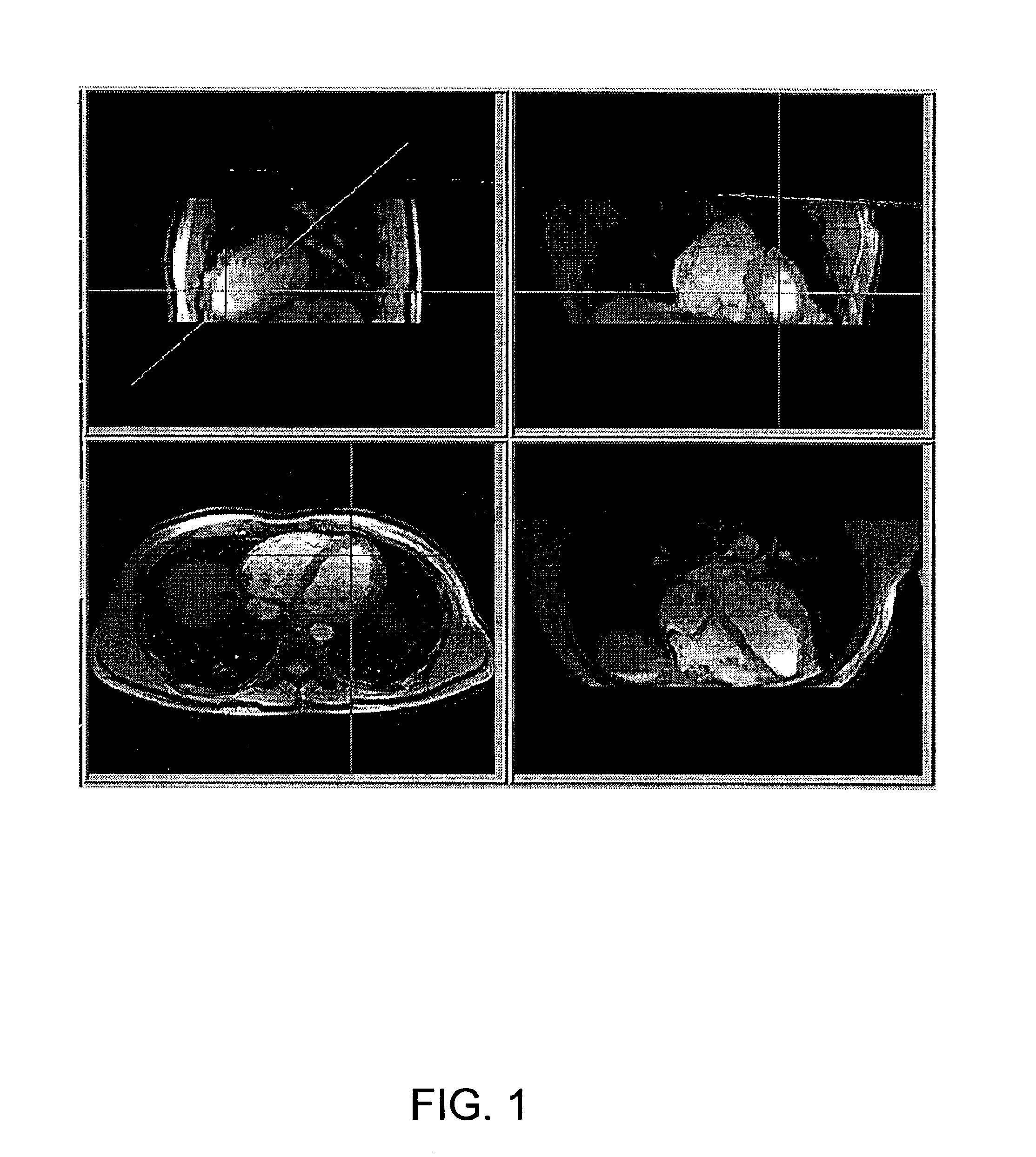
[0032]FIG. 1 shows three localizer images displayed on a screen, where the images include intersection lines as overlay graphics depicting the anticipated location and orientation of the next scan, and the geometry of a new image, according to the prior art. The geometry of a new image, shown in the lower right corner, is defined by editing intersection line graphics in one or more existing views. This approach is used both in image reformatting, illustrat...


PUM


Abstract

Apparatuses, methods and computer program products for scan plane geometry definition in tomographic data acquisition via an interactive three-dimensional (3-D) graphical operator interface. The apparatuses, methods and computer program products are initially proposed for use in cardiac MRI, but have a much broader area of application. The apparatuses and methods utilize 3-D computer graphics aspect views of slice planes to show a new scan, represented as semi-transparent uniformly-colored planes. Intersections of these planes with opaque texture-mapped gray-level views of previously acquired images enable the orientation of a new scan to be viewed in a much more intuitive fashion. Advantageously, the apparatuses and methods of the present invention provide for more efficient elimination of positional ambiguity that is often associated with conventional 2-D intersection line views. In addition, any misregistration between localizer scans can be detected immediately in the integrated 3-D display by misalignment of anatomy in the previously acquires image planes.

Description

CROSS REFERENCE TO RELATED APPLICATION[0001]This application claims priority to and the benefit of the filing date of provisional application entitled “Methods for Display and Visually Driven Definition of Tomographic Image Planes in Three-Dimensional Space,” assigned Ser. No. 60 / 135,368 and filed May 21, 1999, which is hereby incorporated by reference.FIELD OF THE INVENTION[0002]The present invention generally relates to 3-dimensional tomographic imaging, and more particularly, to systems, methods and computer program products facilitating the display and visually driven definition of tomographic image planes in three-dimensional space.BACKGROUND OF THE INVENTION[0003]Tomographic imaging involves the acquisition of data that depict a map of some physical features along cross-sections through a volume in three-dimensional space. Tomography is a technique for generating images of a predetermined plane section of a solid object while blurring out the images of other planes. Several im...

Claims


Application Information

Patent Timeline
Patent Type & Authority Patents(United States)
IPC IPC(8): G06K9/00G06T17/40
CPCG06T19/00G06T2210/41G06T2219/2012G06T2219/028G06T2219/008
Inventor BRUMMER, MARIJN E.
Owner UNIV EMORY
Why Eureka
Try Eureka