Full-field three-dimensional measurement method

a three-dimensional measurement and full-field technology, applied in the direction of measuring devices, instruments, using optical means, etc., can solve the problems of poor accuracy, limited extraction phase accuracy, slow and unpractical real-time 3-d shape measurement, etc., to achieve simple computation, reduce the effect of processing speed and fewer images

Inactive Publication Date: 2007-09-06
UNIVERSITY OF WATERLOO
View PDF7 Cites 130 Cited by
  • Summary
  • Abstract
  • Description
  • Claims
  • Application Information

AI Technical Summary

Benefits of technology

[0030] The present invention seeks to solve problems, with existing 3-D surface-shape measurement, that occur in respect of speed of measurement, ambiguity in determining correspondence between patterns and the real object or scene surface when repeated patterns are used, and in depth resolution. The inventive two-step triangular-pattern phase-shifting method for 3-D surface-shape measurement presents a new efficient intensity-ratio generation algorithm, which provides faster processing speed for generating 3-D coordinates of an object or scene surface with simpler computation and fewer images required. It improves the depth resolution and has a lower degree of ambiguity problems with the triangular patterns used.
[0031] The two-step triangular-pattern phase-shifting for 3-D surface-geometry measurement combines the advantages of conventional sinusoidal phase-shifting method and conventional intensity ratio methods and only uses two triangular patterns relatively phase-shifted by half of the pitch to reconstruct the 3-D surface. Compared with the conventional sinusoidal phase shifting and trapezoidal phase shifting methods, the inventive method has faster processing speed because of the simple computation of the intensity ratio and because fewer images are used to obtain the intensity ratio. It also has a better depth resolution compared to conventional intensity-ratio based methods and a lower degree of ambiguity problems when the intensity ratio ramp is repeated to reduce sensitivity to noise. The inventive method therefore has the potential for faster real-time 3-D surface measurement.

Problems solved by technology

Furthermore, they are slow and not practical for real-time 3-D shape measurement.
Multiple-stripe methods speed up the data acquisition, but suffer from a correspondence problem (cf.
This method has the advantage of fast processing speed, but the accuracy is poor and the problem of ambiguity arises for measuring objects with discontinuous surface shape if the intensity-ratio ramp is repeated (cf.
In these cases, the accuracy of the extracted phase is limited by the accuracy of the mechanical shifting process.
The trade-off, however, is that longer time is involved both in image acquisition and processing, which is fairly limited for real-time analysis.
In order to separate the pure phase information in the frequency domain, the Fourier transform usually uses carrier fringes; this poses difficulty in practice in trying to accurately control the frequency of the carrier fringe.
Another significant limitation of the Fourier transform technique is its inability to handle discontinuities.
Moreover, the complicated mathematical calculation of Fourier transforms is computationally intensive and makes the technique unsuitable for high-speed 3-D shape measurement.
For phase-shifting techniques, sequentially projecting and grabbing images consume time especially for more phase-shift procedures.
However, the drawback of this method is that the measurement accuracy is lower because the accuracy is dependent on the number of images (of Huzug No. 1, supra; and Morimoto, supra).

Method used


Image

  • Full-field three-dimensional measurement method
  • Full-field three-dimensional measurement method
  • Full-field three-dimensional measurement method

Examples


Embodiment Construction

[0072] The present invention will be described for the purposes of illustration only in connection with certain embodiments. However, it is to be understood that other objects and advantages of the present invention will be made apparent by the following description of the drawings according to the present invention. While a preferred embodiment is disclosed, this is not intended to be limiting. Rather, the general principles set forth herein are considered to be merely illustrative of the scope of the present invention and it is to be further understood that numerous changes may be made without straying from the scope of the present invention.

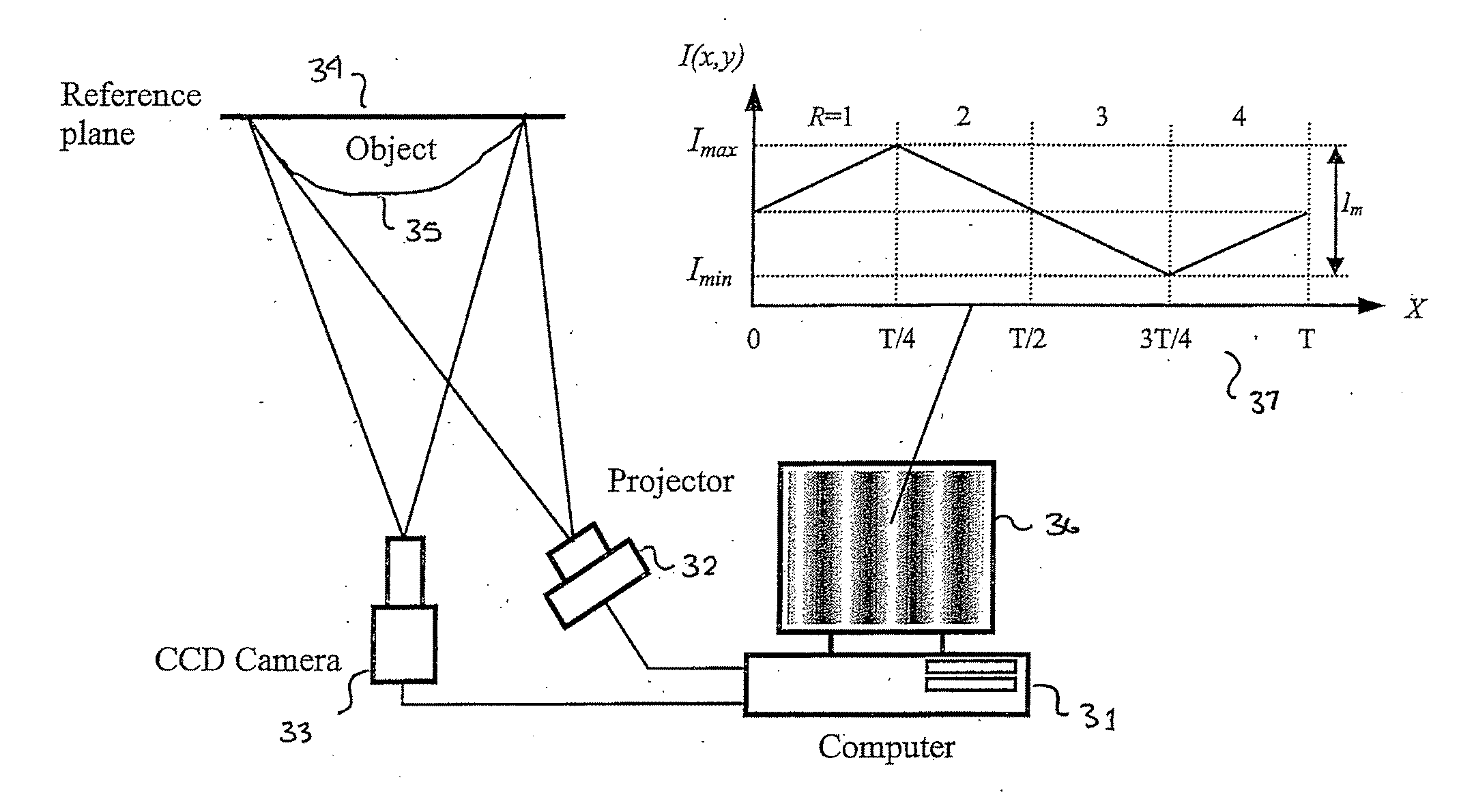
[0073] Referring now to FIG. 3, there is shown a simple schematic diagram of the inventive triangular phase-shifting fringe-projection measurement apparatus, shown generally at 30. It consists of a computer 31, a video projector 32, a CCD camera 33, and a flat reference plane 34 for calibration. The projector 32 is used to project a triangula...


PUM


Abstract

A method and system for full-field fringe-projection for 3-D surface-geometry measurement, referred to as “triangular-pattern phase-shifting” is disclosed. A triangular grey-scale-level-coded fringe pattern is computer generated, projected along a first direction onto an object or scene surface and distorted according to the surface geometry. The 3-D coordinates of points on the surface are calculated by triangulation from distorted triangular fringe-pattern images acquired by a CCD camera along a second direction and a triangular-shape intensity-ratio distribution is obtained from calculation of the captured distorted triangular fringe-pattern images. Removal of the triangular shape of the intensity ratio over each pattern pitch generates a wrapped intensity-ratio distribution obtained by removing the discontinuity of the wrapped image with a modified unwrapping method. Intensity ratio-to-height conversion is used to reconstruct the 3-D surface coordinates of the object. Intensity-ratio error compensation involves estimating intensity-ratio error in a simulation of the measurement process with both real and ideal captured triangular-pattern images obtained from real and ideal gamma non-linearity functions. A look-up table relating the measure intensity-ratio to the corresponding intensity-ratio error is constructed and used for intensity-ratio error compensation. The inventive system is based on two-step phase-shifting but can be extended for multiple-step phase-shifting.

Description

FIELD OF THE INVENTION [0001] The present invention relates to three-dimensional surface-geometry or shape measurement useful in building a digital or mathematical representation of an object or environment for which the geometry is unknown. BACKGROUND OF THE INVENTION [0002] Three-dimensional (3-D) surface-geometry or shape measurement is useful to build a digital or mathematical representation of an object or environment for which the geometry is unknown. One of the most widely used techniques to obtain the 3-D shape of an unknown object is using structured light. By projecting a known light pattern (stripe, grid, or more complex shape) onto an object, the 3-D coordinates of points on the object surface can be calculated by triangulation from images acquired from another direction. FIG. 1 illustrates this triangulation principle. In the example shown in FIG. 1, a laser line is projected onto a scanned object. The light is scattered from the object surface and the image of the curv...

Claims


Application Information

Patent Timeline
Patent Type & Authority Applications(United States)
IPC IPC(8): G01B11/24
CPCG01B11/254G01B11/2527
Inventor JIA, PEIRONGKOFMAN, JONATHAN DAVIDENGLISH, CHAD
Owner UNIVERSITY OF WATERLOO
Why Eureka
Try Eureka