Sealed rolliing bearing

a rolling bearing and seal technology, applied in the direction of bearing components, shafts and bearings, bearing seals, etc., can solve the problems of uneven interference of seal lip, and achieve the effect of improving the sealability of sealed rolling bearings and preventing the entry of muddy water

Active Publication Date: 2010-02-18
NTN CORP
View PDF2 Cites 1 Cited by
  • Summary
  • Abstract
  • Description
  • Claims
  • Application Information

AI Technical Summary

Benefits of technology

[0010]By setting the circumferential flatness of the seal surface that is in contact with the seal lip to 5 to 20 μm, the interference of the seal lip provided at the radially inner portion of each seal member becomes uniform in the circumferential direction of the seal surface. Also, when the outer race rotates at high speed, the axial movement of the seal surface is minimum, so that the edge of the seal lip can smoothly follow the axial movement of the seal surface. This improves sealability of the sealed rolling bearing to such an extent that the entry of muddy water can be substantially completely prevented.

Problems solved by technology

Thus, the interference of the seal lip is uneven in the circumferential direction of the seal surface.

Method used


Image

  • Sealed rolliing bearing
  • Sealed rolliing bearing
  • Sealed rolliing bearing

Examples


Embodiment Construction

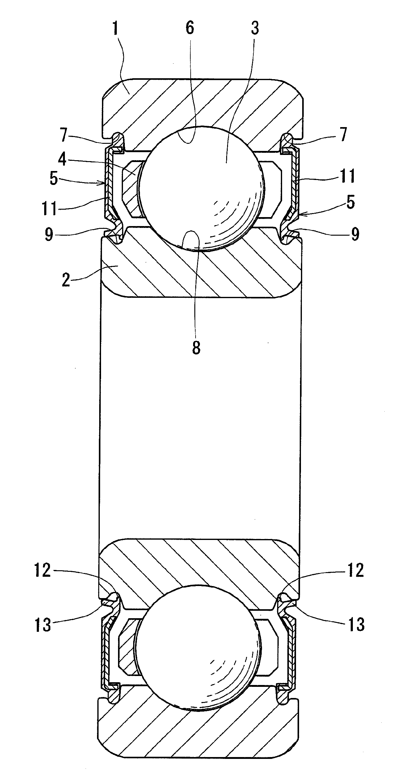
[0029]The embodiments of this invention are now described with reference to the drawings. The sealed roller bearing shown in FIG. 1 comprises an outer race 1, an inner race 2 mounted inside the outer race 1, rolling elements 3 supporting the inner and outer races 2 and 1 so as to be rotatable relative to each other, a retainer 4 supporting the rolling elements 3, and a pair of seal members 5 sealing a bearing space defied between opposed surfaces of the inner and outer races 2 and 1.

[0030]The outer race 1 has on its radially inner surface a raceway 6 and a pair of seal grooves 7 on both side of the raceway 6. The inner race 2 has on its radially outer surface a raceway 8 radially opposed to the raceway 6. The rolling elements 3 are disposed between the inner race raceway 8 and the outer race raceway 6.

[0031]The inner race 2 is further formed with a pair of annular grooves 9 on its radially outer surface on both sides of the raceway 8. The annular grooves 9 each have an axially inner...


PUM


Abstract

The object is to provide a sealed rolling bearing which has high sealability sufficient to substantially completely prevent entry of muddy water.
The radially outer portion of the seal member 5 is fitted in each of a pair of seal grooves 7 formed in the radially outer surface of an outer ring 1 at both ends thereof. A seal lip 12 formed at the radially inner portion of each seal member 5 is brought into elastic contact with an inner seal surface 10 of each of annular grooves 9 formed in the radially outer surface of an inner ring 2 at both ends thereof. The contact portion X of the seal surface 10 that is in elastic contact with the seal lip 12 has a circumferential flatness A of 5 to 20 μm. With this arrangement, it is possible to improve sealability at the contact portions, thereby preventing entry of e.g. muddy water into the bearing.

Description

TECHNICAL FIELD[0001]This invention relates to a sealed rolling bearing.BACKGROUND ART[0002]Bearings for electromagnetic clutches in car air-conditioners, bearings for pulleys and alternators in cars are exposed e.g. to rainwater and muddy water during use. Thus, for these bearings, sealed rolling bearings are used to prevent entry of rainwater and muddy water.[0003]Conventional sealed rolling bearings include one comprising an outer race having an outer raceway formed on its radially inner surface, and seal grooves formed in its radially inner surface on both sides of the outer raceway, an inner race having an inner raceway formed on its radially outer surface, and annular grooves formed in its radially outer surface on both sides of the inner raceway and each having an inner seal surface, rolling elements mounted between the inner and outer raceways, and seal members having their radially outer portions fitted in the respective seal grooves, and each having at its radially inner p...

Claims


Application Information

Patent Timeline
Patent Type & Authority Applications(United States)
IPC IPC(8): F16C33/76
CPCF16C33/7853F16J15/3204F16C33/583F16J15/3456F16J15/3252F16C19/06
Inventor MURAMATSU, MAKOTO
Owner NTN CORP
Why Eureka
Try Eureka