Composite profile provided with a support body made of a light metal material and a profiled strip and a method for producing said profile

a technology of light metal material and supporting body, applied in the direction of workpiece edge portions, power rails, railway tracks, etc., can solve the problems of undulation on the upper surface of the covering profile, conductor rails, disadvantages, etc., and achieve the effect of reducing the height toleran

Active Publication Date: 2010-02-25
CONSTELLIUM SWITZERLAND
View PDF9 Cites 4 Cited by
  • Summary
  • Abstract
  • Description
  • Claims
  • Application Information

AI Technical Summary

Benefits of technology

This invention has several technical benefits: it allows for longer use of certain parts by making them easier to replace (especially if they become damaged), reduces the risk of damage during installation, and makes sure that all necessary components are always available no matter where in the world the product needs to be made or used.

Problems solved by technology

The technical problem addressed in this patent is to improve the bond between a carrier profile and a profile strip while retaining the economic manufacturing process. Existing methods such as extrusion and clamping have limitations such as detachment of the profile strip from its support profile and undulations on the upper surface of the covering profile. The invention aims to overcome these limitations and improve the bond between the carrier profile and profile strip.

Method used


Image

  • Composite profile provided with a support body made of a light metal material and a profiled strip and a method for producing said profile
  • Composite profile provided with a support body made of a light metal material and a profiled strip and a method for producing said profile
  • Composite profile provided with a support body made of a light metal material and a profiled strip and a method for producing said profile

Examples


Embodiment Construction

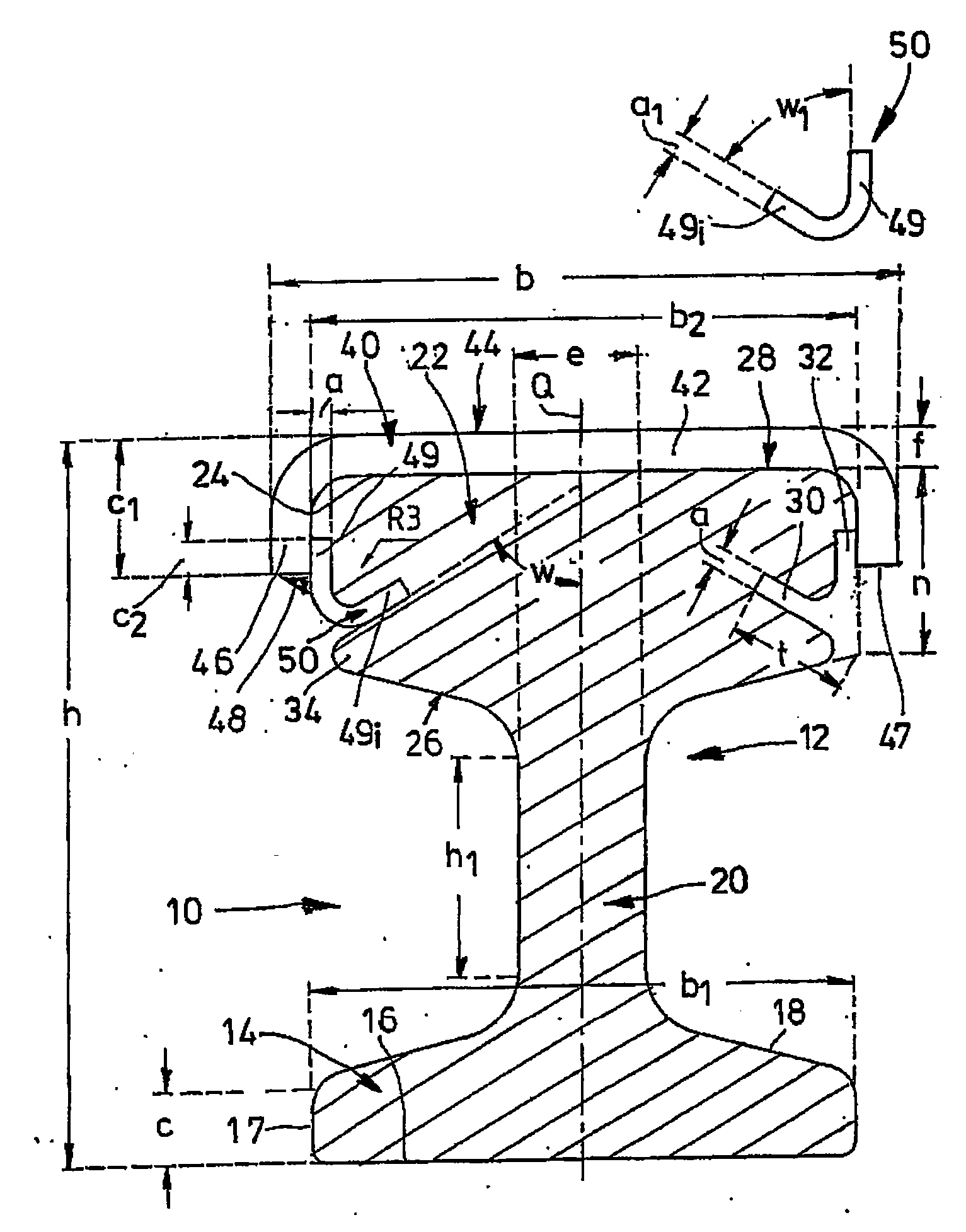
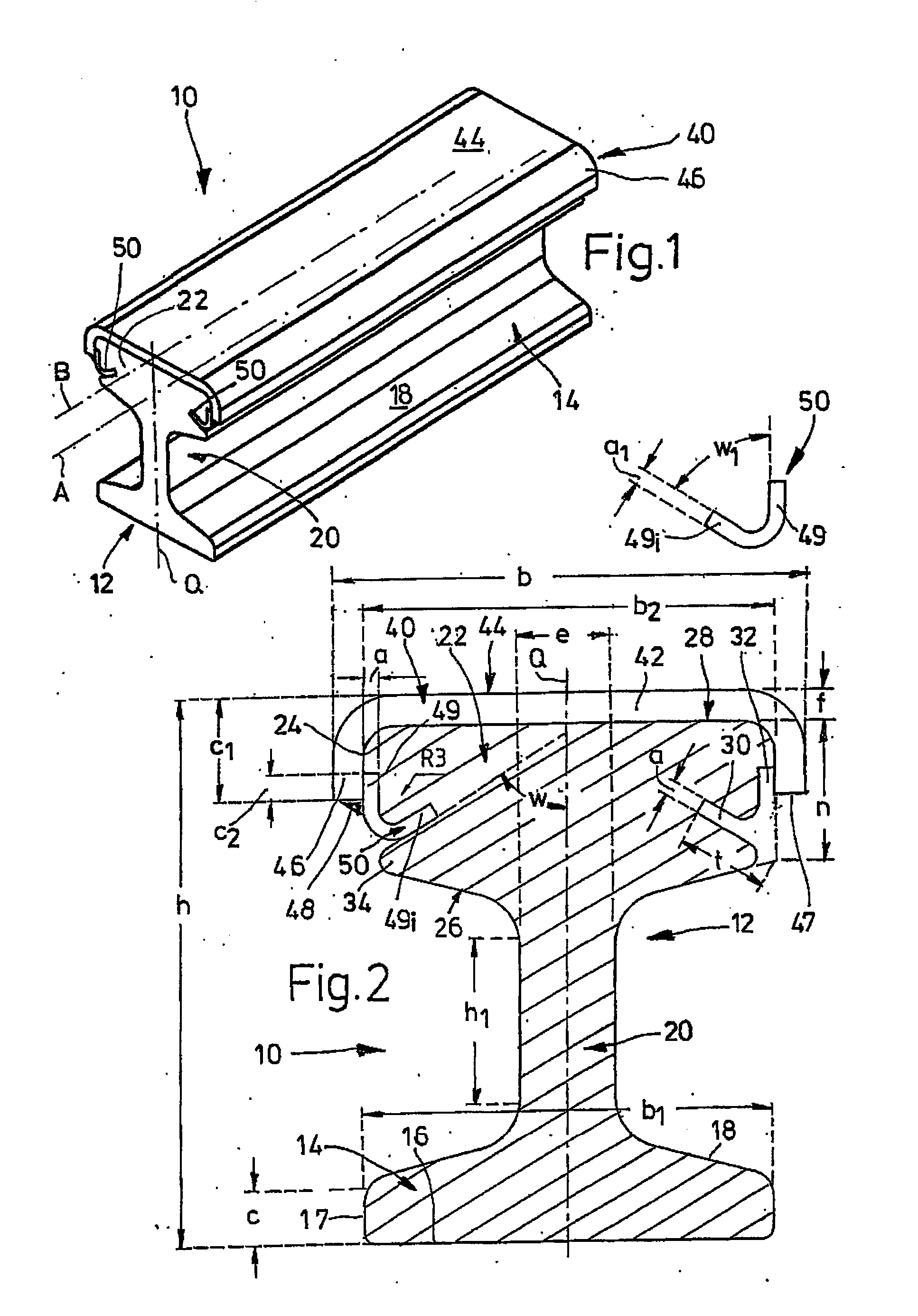
[0041]A composite profile 10 having a height h of 105 mm here and a maximum width b of 92 mm comprises according to FIG. 1 a rail-shaped carrier profile 12 with a rail base 14 and an endless rail head 22 formed integrally on the rail base 14 by means of a rail stem 20. Two longitudinal edges 17 with a height c of 10 mm defining the bottom surface 16 of the rail base 14 run parallel to each other at a distance b1 of 80 mm here.

[0042]From these longitudinal edges 17, the two roof surfaces 18 of the rail base 14 are inclined slightly upwards to the cross-sectional centre axis Q traversing the longitudinal axis A of the composite profile 10, and merge with that rail stem 20 having a height h1 of approximately 30 mm and a thickness e of approximately 18 mm. From the upper end of the rail stem 20 extend the lower surfaces 26 of the rail head 22 which are inclined approximately upwards to the longitudinal edges 24 of this rail head 22, which has a width b2 of 78 mm and of which the outside...


PUM

PropertyMeasurementUnit
Angleaaaaaaaaaa
Angleaaaaaaaaaa
Angleaaaaaaaaaa

Abstract

A composite profile comprising a carrier profile made of a light metal material and a profiled strip which is made of a harder material and covers the top surface of the carrier profile. An insertable bar is added to the profiled strip on each longitudinal side in a position parallel to the direction thereof and is inserted into a lateral slot embodied therein. The insertable bar is firmly connected to the profiled strip thereof by a weld seam.

Description


Claims


Application Information

Patent Timeline
Owner CONSTELLIUM SWITZERLAND
Why Eureka
Try Eureka