Hinged forceps

Inactive Publication Date: 2010-02-25
LUH JOIN Y
View PDF37 Cites 19 Cited by
  • Summary
  • Abstract
  • Description
  • Claims
  • Application Information

AI Technical Summary

Benefits of technology

[0006]In an embodiment, forceps may include at least two arms, one or more finger grips, and a hinge coupling the two arms to each other. At least one finger grip may be positioned on at least one of the arms. The hinge may be positioned at an end of each of the arms. The hinge may restrict the range of motion of the arms with respect to each other. The hinge may function to allow a predetermined separation between the arms of the forceps. In some embodiments, the hinge ma

Problems solved by technology

The hinge may restrict the range of motio

Method used


Image

  • Hinged forceps
  • Hinged forceps
  • Hinged forceps

Examples


Example

[0015]While the invention is susceptible to various modifications and alternative forms, specific embodiments thereof are shown by way of example in the drawings and will herein be described in detail. The drawings may not be to scale. It should be understood that the drawings and detailed description thereto are not intended to limit the invention to the particular form disclosed, but to the contrary, the intention is to cover all modifications, equivalents and alternatives falling within the spirit and scope of the present invention as defined by the appended claims.

DETAILED DESCRIPTION OF EMBODIMENTS

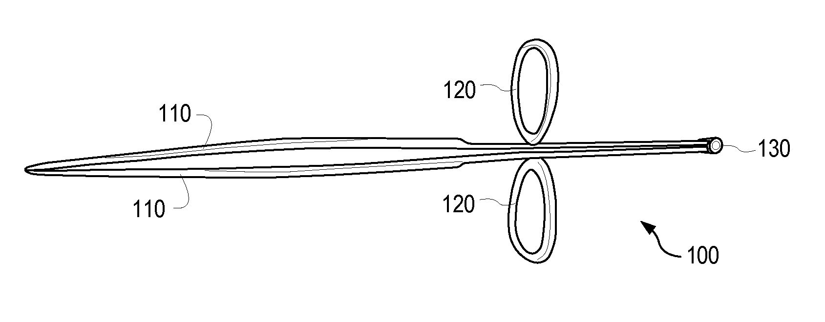
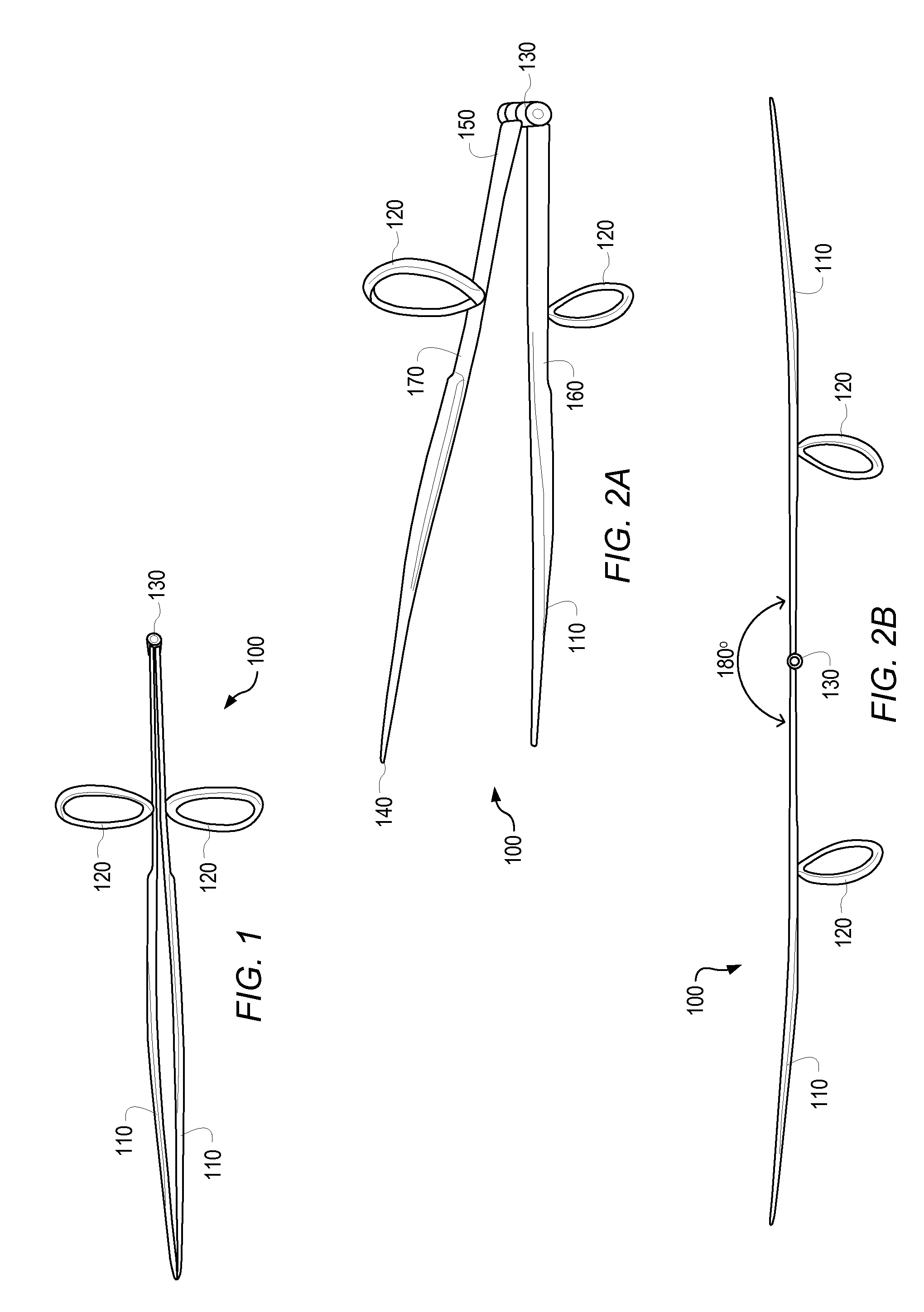
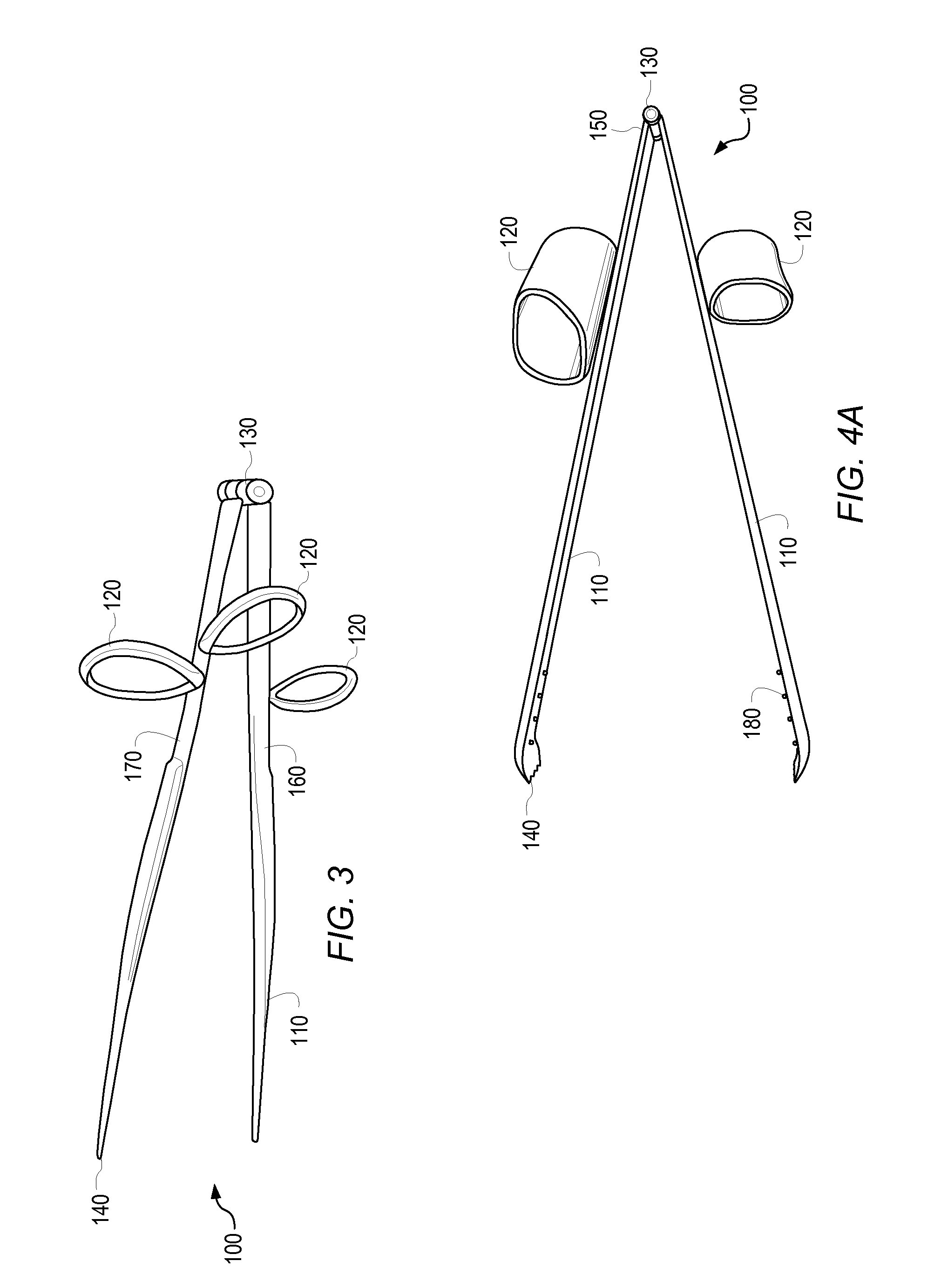
[0016]In various embodiments, forceps 100 includes arms 110, one or more finger grips 120, and a hinge 130, as depicted in FIG. 1. Forceps may be used to hold objects, close areas, and / or open areas. For example, during surgery, forceps may be used to hold a blood vessel, an organ, or tissue; clamp an area, an organ, or a blood vessel closed; or open an area for surgery. Forceps, such...


PUM


Abstract

In some embodiments, a forceps may include at least two arms, at least one finger grip, and a hinge. Finger grips may be positioned on an arm. A hinge may couple two or more arms together In an embodiment, a hinge may allow 60 degrees of separation between coupled arms. A hinge may allow uninhibited movement of one arm relative to the other arm.

Description

BACKGROUND[0001]1. Field of the Invention[0002]The present invention relates to forceps. More particularly, the invention relates to forceps that include finger grips and / or hinges.[0003]2. Brief Description of the Related Art[0004]Forceps are commonly used in medical procedures, engineering applications, food-service applications, and beauty applications. Forceps usually include two arms fused together at an end or joined with a spring mechanism. The fused joint or spring mechanism causes inhibited motion of the arms of the forceps. In such instances, movement of the arms with respect to each other is resisted until a force is applied to the forceps to overcome the resistive force of the spring mechanism or fused joint. Thus, a user must constantly apply pressure to the arms to retain the altered position of the arms with respect to each other. In addition, a user must maintain pressure on the forceps to control the forceps while applying pressure to the forceps to retain an object...

Claims


Application Information

Patent Timeline
IPC IPC(8): A61B17/28
CPCA45D26/0066A61B2017/00438A61B17/30A47G21/10A47J43/283
Inventor LUH, JOIN Y.
Owner LUH JOIN Y
Why Eureka
Try Eureka