
Disk conveyance device and disk device

Inactive Publication Date: 2010-02-25
PIONEER CORP
View PDF15 Cites 3 Cited by
  • Summary
  • Abstract
  • Description
  • Claims
  • Application Information

AI Technical Summary

Benefits of technology

[0009]A disc device according to the aspect of the invention includes. the disc transfer device described above; the holder for holding the recording medium; and an information processor for p

Problems solved by technology

Accordingly, for example, when the drawer is completely ejected (see FIGS. 1 and 3 of Patent Document 1), the drawer is likely to incline downward due to impact given to the drawer and the drawer's own weight, so that strength of the drawer is unstable.
Consequently, it is difficult to center the disc on a turntable.

Method used


Image

  • Disk conveyance device and disk device
  • Disk conveyance device and disk device
  • Disk conveyance device and disk device

Examples


first exemplary embodiment

Arrangement of Disc Device

[0046]A disc device according to a first exemplary embodiment of the invention will be described below with reference to the attached drawings.

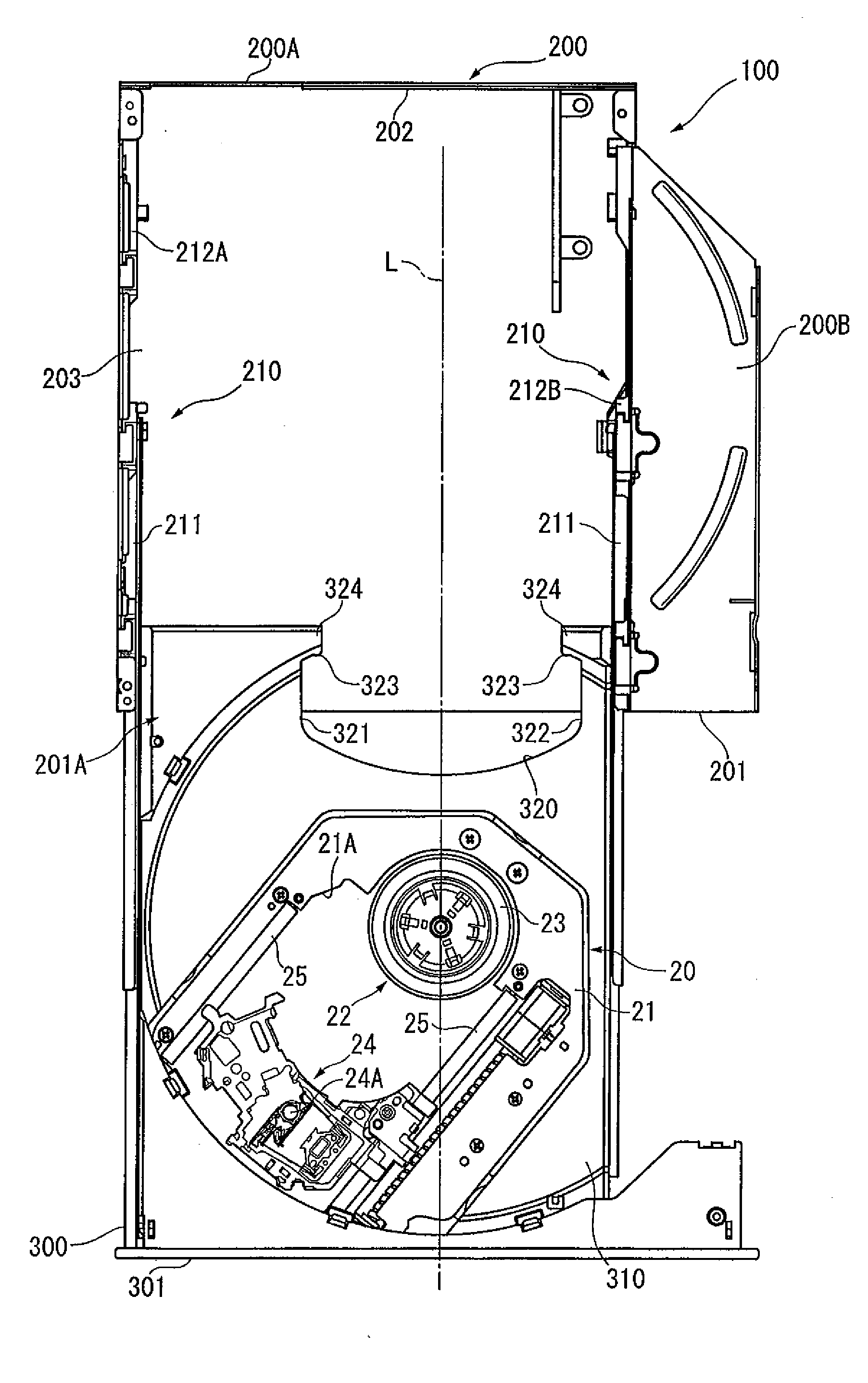
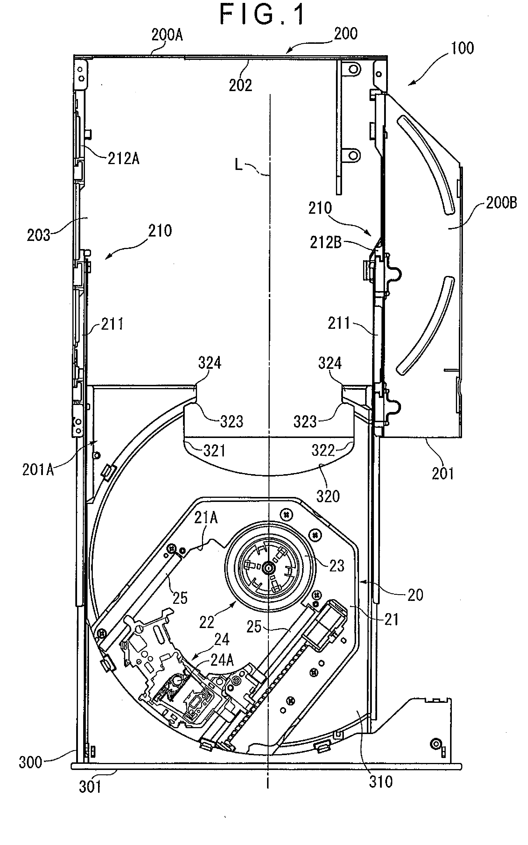
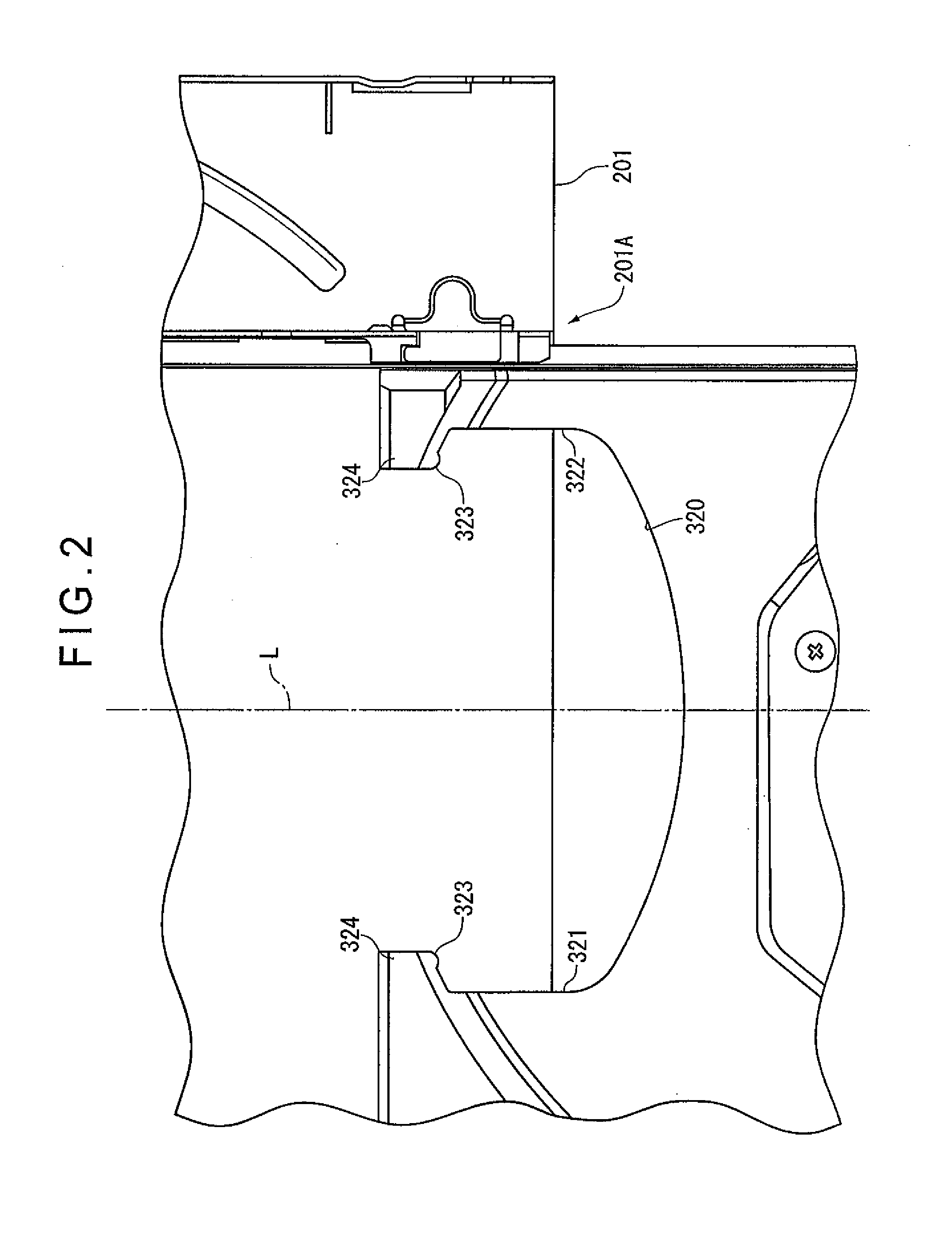
[0047]FIG. 1 is a plan view showing an arrangement of a tray and a case when the tray is ejected out of the case in the disc device according to the first exemplary embodiment of the invention. FIG. 2 is a plan view showing a vicinity of a rear face of the tray. FIG. 3 is a cross section showing the vicinity of the rear face of the tray.

[0048]In FIGS. 1 and 2, a numeral 100 represents the disc device functioning as a disc transfer device as well, and is a so-called slim disc device (or slim disc drive) installed in an electrical equipment such as a portable personal computer.

[0049]The disc device 100 conducts at least one of reading processing as information processing that reads out information recorded on a recording surface (not shown), and recording processing as information processing that records various pieces...

second exemplary embodiment

Arrangement of Disc Device

[0097]A disc device 100A according to a second exemplary embodiment of the invention will be described below with reference to the attached drawings.

[0098]FIG. 7 is a plan view showing a vicinity of a rear face of a tray in the disc device according to the second exemplary embodiment. FIG. 8 is a lateral cross section showing the vicinity of the rear face of the tray in the disc device according to the second exemplary embodiment. FIG. 9 is a lateral cross section in the disc device according to the second exemplary embodiment when the tray is housed in the case. It should be noted that the same numerals are applied to the same arrangement as that of the first exemplary embodiment to omit or simplify descriptions of the numerals.

[0099]Similarly to the first exemplary embodiment, the disc device 100A according to the second exemplary embodiment includes a case 200 and a tray 300.

[0100]Similarly to the first exemplary embodiment, the case 200 is formed substa...


PUM


Abstract

A disc device includes. a case having an opening; and a tray that is movable to and retractable from the case and is provided on one surface thereof with an arc recess capable of holding an optical disc. The tray includes a cutout portion that is provided near a rear face of the arc recess and guides an inserted distal end of the optical disc toward a bottom side of the tray lower than an upper face of the arc recess.

Description

TECHNICAL FIELD[0001]The present invention relates to a disc transfer device for transferring a disc recording medium, and a disc device.BACKGROUND ART[0002]There has been known a disc device that mounts a disc on a tray to transfer the disc into the device (see, for instance, Patent Document 1).[0003]Patent Document 1 discloses that an optical disc device including a drawer in which a disc driving mechanism is mounted is slidably supported on a bottom plate of the optical disc device by guide rails provided on both sides of the drawer. This optical disc device is arranged so that the drawer is locked when whole of the drawer is ejected out of the bottom plate during ejection of the drawer (see FIGS. 1 and 3 of Patent Document 1).[0004]Patent Document 1. JP-A-2006-190352DISCLOSURE OF THE INVENTIONProblems to Be Solved by the Invention[0005]In a typical disc device as disclosed in Patent Document 1 above, whole of the tray is supported by the two guide rails provided on the both side...

Claims


Application Information

Patent Timeline
IPC IPC(8): G11B17/04G11B33/04
CPCG11B17/056
Inventor ITO, HIDEOHOSHINAKA, EIJIICHIKAWA, YOSHIHIROISHIKAWA, TOMONARI
Owner PIONEER CORP
Learn More