Stand Up and Kneel Seat

Active Publication Date: 2010-03-04
INTIER AUTOMOTIVE INC
View PDF10 Cites 10 Cited by
  • Summary
  • Abstract
  • Description
  • Claims
  • Application Information

AI Technical Summary

Benefits of technology

[0010]According to one aspect of the invention, a seat assembly is provided for supporting an occupant above a floor in an automotive vehicle. The seat assembly includes a seat back and seat cushion. A base is configured to be mounted to the floor of the vehicle. A forward link pivotally extends between the seat cushion and the base. A control bracket has a pair of pivotal links forming a four bar connection with the base. A control link pivotally extends between the seat cushion and the control bracket. The seat back is operatively coupled to the control bracket. The seat ba

Problems solved by technology

Thus, passengers do not have direct access to the third row seating.
However, movement of the second row seating in this manner can be difficult for some passengers, and the passageway for ingress and egress is often uncomfortably small

Method used


Image

  • Stand Up and Kneel Seat
  • Stand Up and Kneel Seat
  • Stand Up and Kneel Seat

Examples


Embodiment Construction

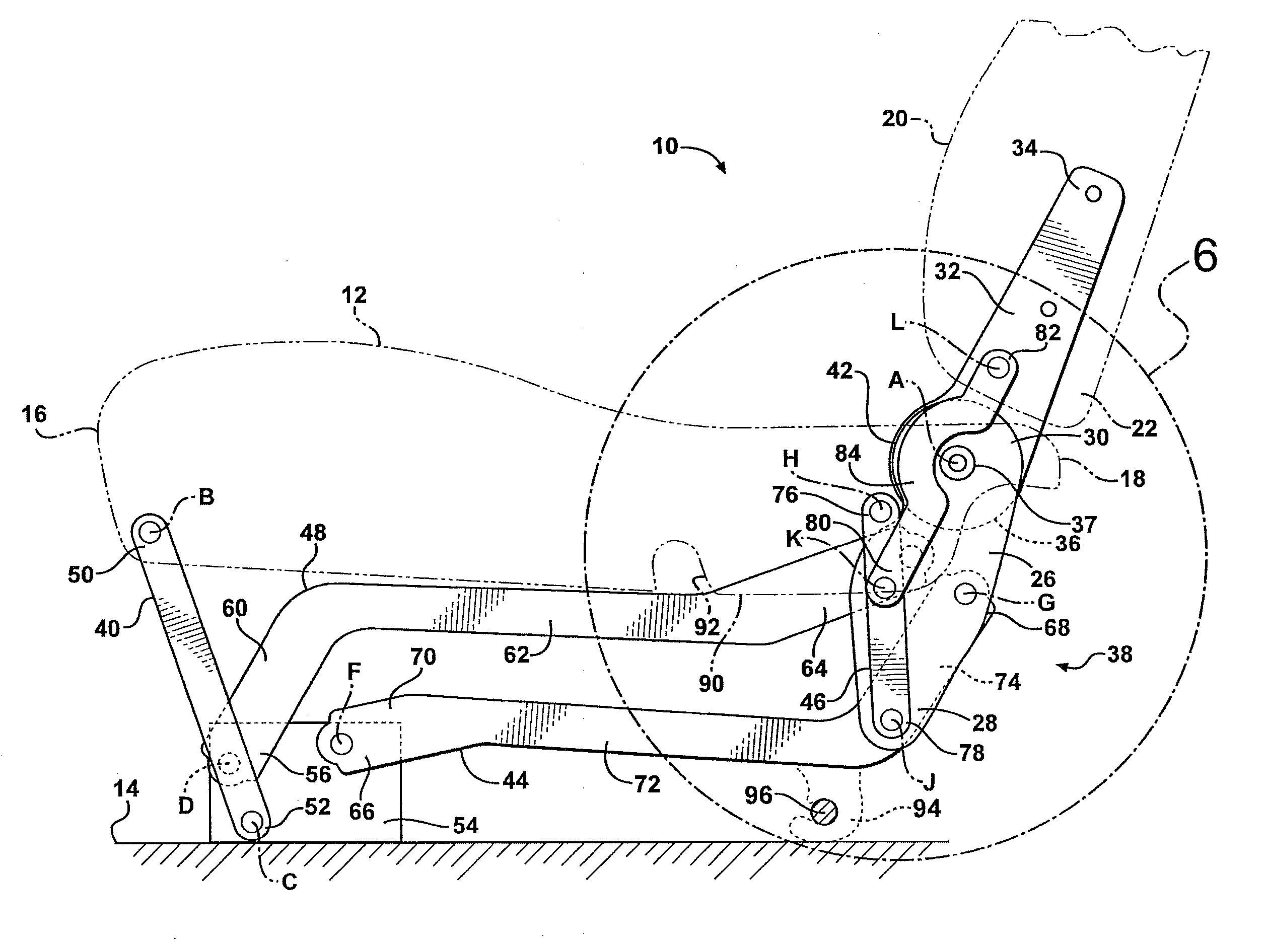
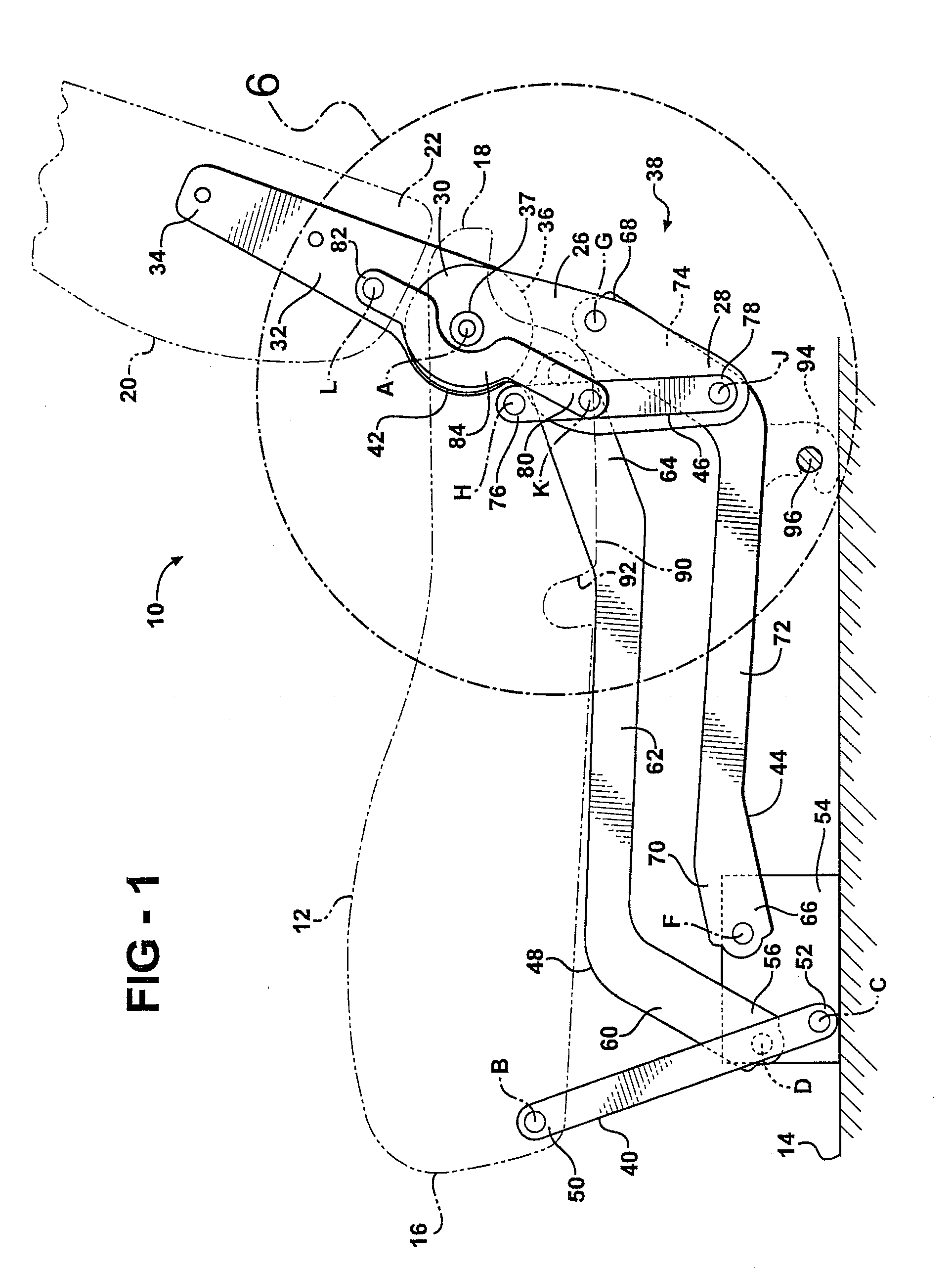
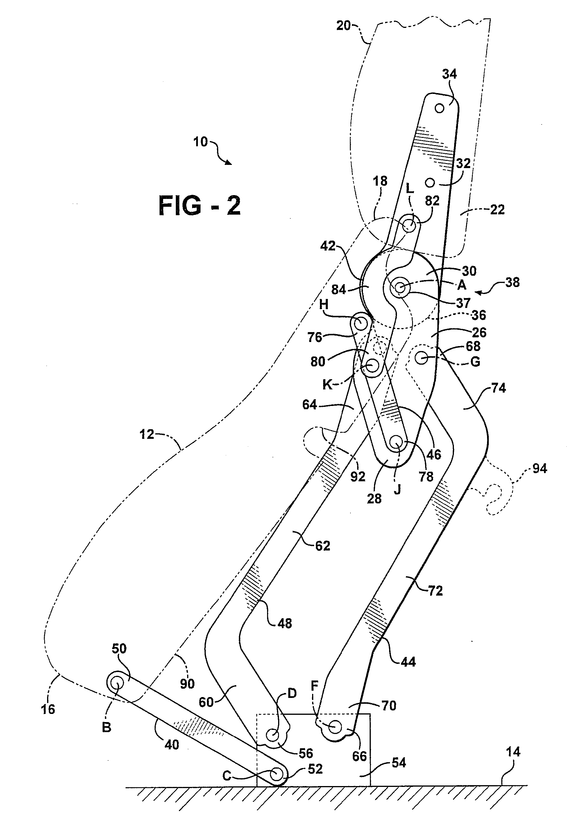
[0020]Referring to FIG. 1, a seat assembly for an automotive vehicle is generally shown at 10. The seat assembly 10 is shown in a seating position and includes a seat cushion 12 for supporting a seat occupant above a floor 14 in the vehicle. The seat cushion 12 extends between a front end 16 and a rear end 18. The seat assembly 10 also includes a seat back 20 for supporting a back of the seat occupant. The seat back 20 extends between a lower end 22 and an upper end 24, as shown in FIG. 5.

[0021]While only one side of the seat assembly 10 is shown and will be described in detail, it is appreciated that both an inboard side and an outboard side are substantially the same. Referring to FIGS. 1 through 8, the outboard side of the seat assembly 10 is shown. A control bracket 26 is disposed at the rear end 18 of the seat cushion 12. The control bracket 26 extends between a first end 28 and a second end 30.

[0022]A seat back bracket 32 extends between an upper end 34 and a lower end 36. The...


PUM


Abstract

A seat assembly includes a seat back and seat cushion. A forward link pivotally extends between the seat cushion and base. A control bracket has a pair of pivotal links forming a four bar connection with the base. A control link pivotally extends between the seat cushion and control bracket. A seat back operatively coupled to the control bracket has a recliner mechanism for selectively pivoting the seat back between a forwardly folded position and a plurality of reclined seating positions. A guide link pivotally extends between the seat back and control link. Forward rotational movement of the seat cushion urges the seat back to rotate relative to the seat cushion moving the seat assembly to a stand-up position. Pivoting the seat back to the forwardly folded position urges the seat cushion to move forwardly and lower relative to the base moving the seat assembly to a kneeling position.

Description

CROSS REFERENCE TO RELATED APPLICATION[0001]This application claims priority to and all the benefits of U.S. Provisional Application Ser. No. 60 / 880,672, filed on Jan. 16, 2007 and entitled “Stand up and kneel seat.”BACKGROUND OF THE INVENTION[0002]1. Field of the Invention[0003]The invention relates to a seat assembly for an automotive vehicle. More particularly, the invention relates to a seat assembly that is movable between a seating position, a stand-up position, and a kneeling position.[0004]2. Description of Related Art[0005]It is common in certain mini-van and sport utility vehicles to provide third row seating. Typically, the vehicle includes a pair of front doors adjacent front row seating and a pair of rear doors located adjacent second row seating. The third row seating is located at the generally furthermost rear portion of the vehicle and is not located adjacent a door opening. Thus, passengers do not have direct access to the third row seating.[0006]To provide access ...

Claims


Application Information

Patent Timeline
IPC IPC(8): B60N2/10B60N2/02B60N2/22B60N2/20B60N2/04
CPCB60N2/22B60N2/3011B60N2/36B60N2/3065B60N2/309B60N2/3031B60N2/04B60N2/10B60N2/20
Inventor HOLDAMPF, CARL J.
Owner INTIER AUTOMOTIVE INC
Why Eureka
Try Eureka