Adjustable kneeling support pad

a kneeling support and adjustable technology, applied in the field of kneeling support pads, can solve the problems of troublesome kneeling and standing up, rigid support objects, and difficult storage of l-shaped structures, and achieve the effect of relieving discomfort on the knees of peopl

Active Publication Date: 2014-11-18
MOFFAT GARY
View PDF16 Cites 6 Cited by
  • Summary
  • Abstract
  • Description
  • Claims
  • Application Information

AI Technical Summary

Benefits of technology

[0009]It is an object of the present invention to provide a portable kneeling support pad used to relieve discomfort on a person's knee when kneeling. The support pad includes a flat rectangular base with a resilient top surface. Attached near one end of the base is a detachable, perpendicularly aligned, support pole with a horizontally aligned grip handle attached to the pole's distal end. The base includes a support pole bore with a coaxially aligned stub partially inserted therein that extends upward and perpendicular to the base's stop surface. In one embodiment, the stub is designed to slide over the proximal end of the support pole thereby holding the support pole in a perpendicular alignment over the base. Attached to the distal end of the support post is a handle with a horizontal gripping member that enables the user to press against when standing to an upright position.
[0010]Disposed around the upper end of the stub is an adjustable clamp that when loosened, allows the user to selectively rotated the support pole 360 degrees around the stub and to selectively lower and raise the support pole into the stub to decrease or increase the height of the hand grip over the base to a desired amount. When the support pole is removed from the stub, the support base may be longitudinally aligned on the base and stacked against the top surface and an strap may be wrapped around the base and the support pole to hold them together.

Problems solved by technology

For some drivers, kneeling down and standing up can also be troublesome.
Although not relevant to the overall ornamental shape, the support pole was securely attached to one end of the pad and fixed in length creating an L-shaped structure that is difficult to store in the jack storage area in the trunk of a motor vehicle or on the shelf in a cabinet with other cleaning products.
When lying in the middle of a room, a rigid support object or surface to support the patient when trying to stand up is not always available.

Method used


Image

  • Adjustable kneeling support pad
  • Adjustable kneeling support pad
  • Adjustable kneeling support pad

Examples


second embodiment

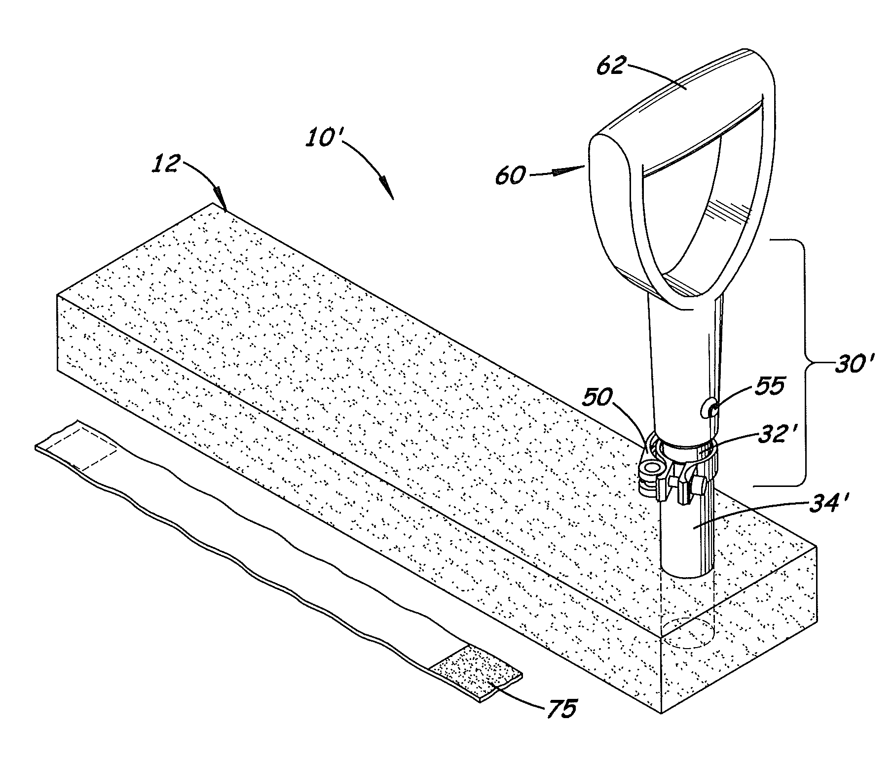
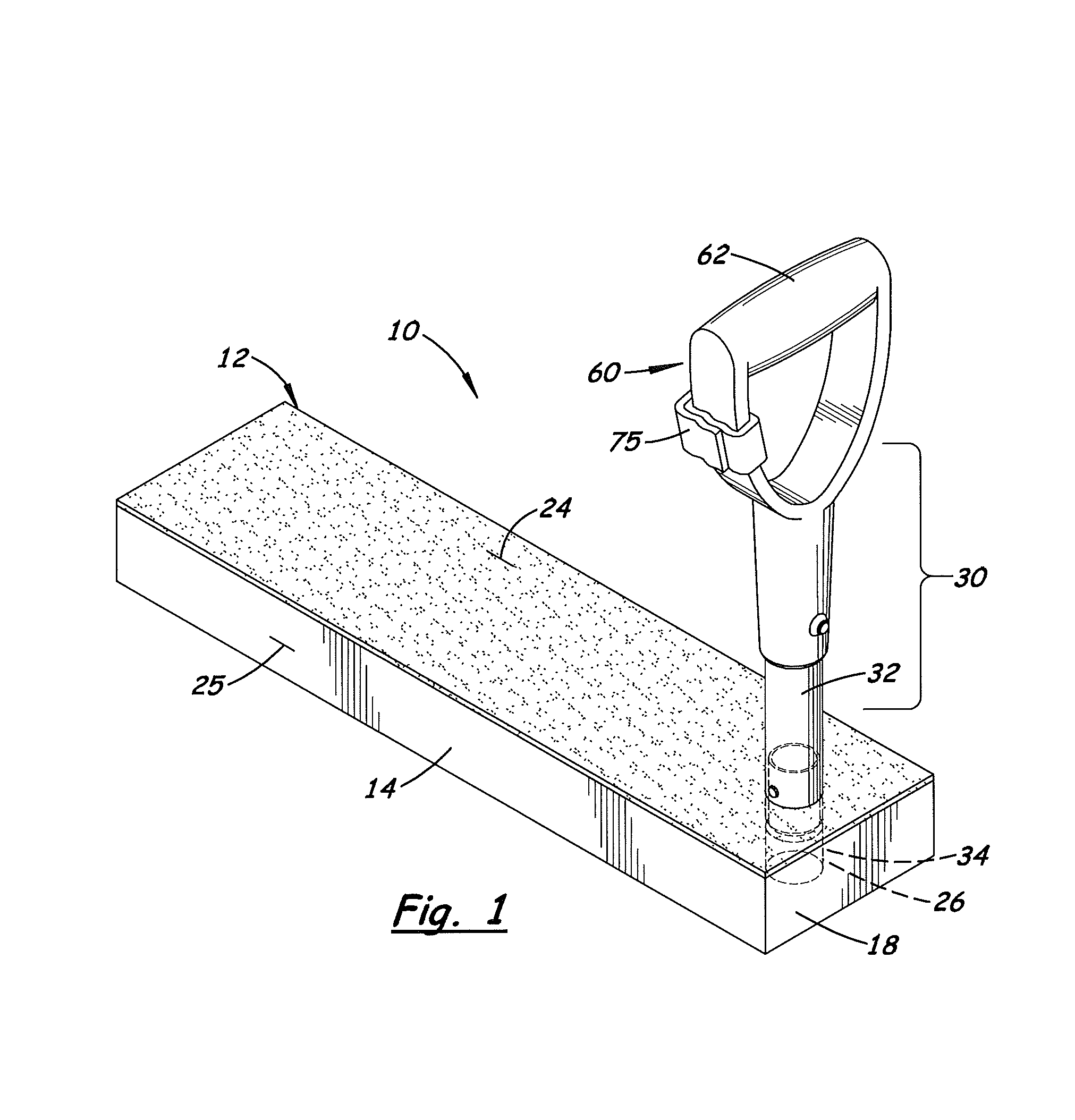
[0020]Referring to the accompanying FIGS. 1-8, there is shown several embodiments of a portable kneeling support pad (denoted by 10 and 10′) each used to relieve discomfort on a person's knee when kneeling and to assist them when standing up. Both embodiments include a removable, support pole 30 with a rigid grip handle 60. In one embodiment, the support pole 30 has a fixed length and fixed orientation. In a second embodiment, the support pole 30 may be selectively adjusted in length and rotated 360 degrees.

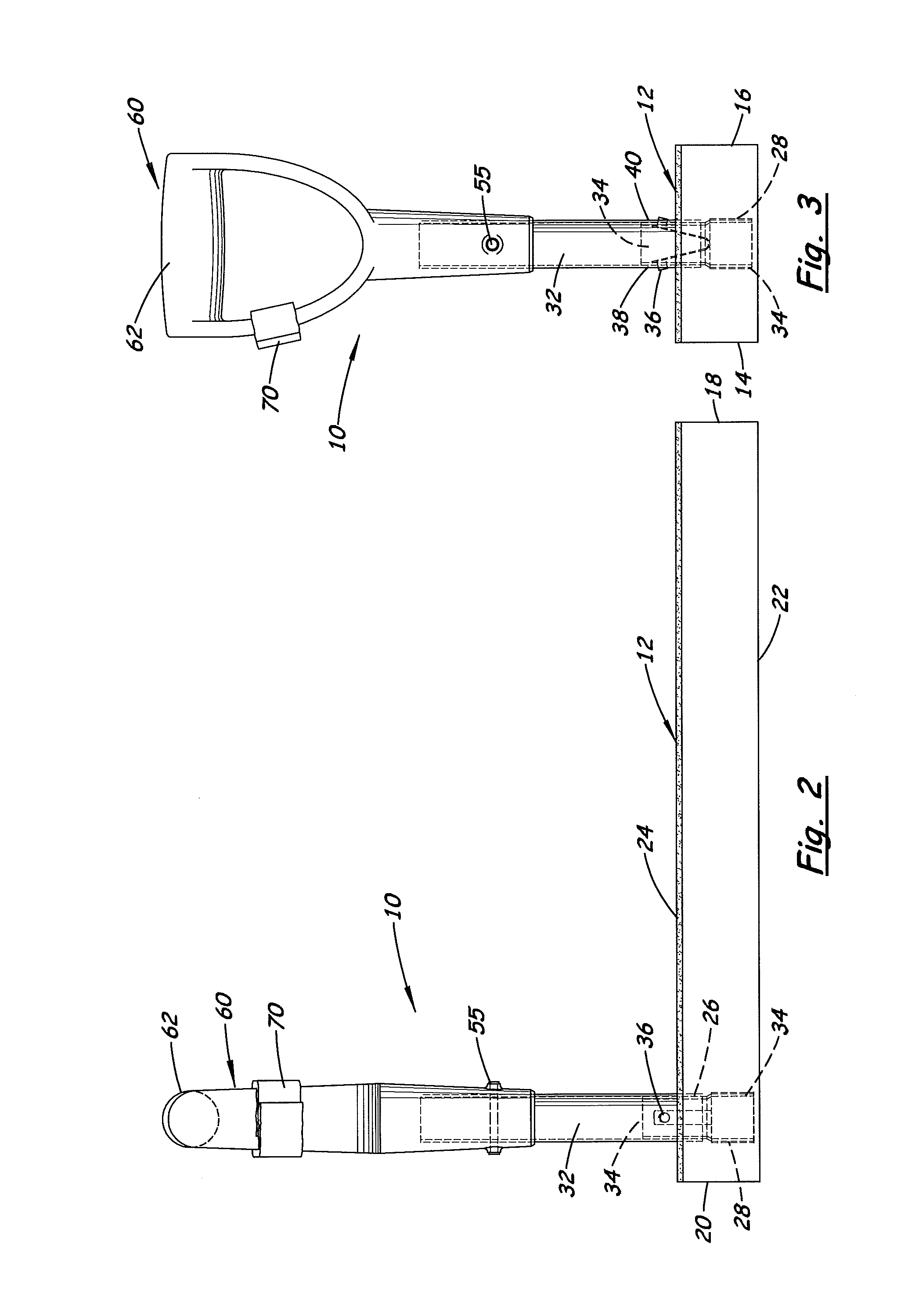
[0021]The support pad 10 includes a flat rectangular base 12 with two parallel side surfaces 14, 16, two parallel end surfaces 18, 20, a flat bottom surface 22 and a resilient top layer 24. Attached near one end of the base 12 is a perpendicularly aligned support pole 30 with a horizontally aligned grip handle 60 attached to the distal end of the support pole 30.

[0022]The support pole 30 is removably attached to the base 12 thereby enabling the support pad 10 to be disassembled a...

first embodiment

[0025]Attached to the stub 34′ is an adjustable clamp 50 that when activated, forces the stub 34′ inward causes the inside surface to press against the outside surface of the upper tube section 32′ of the support pole 30′ thereby fixing the support pole 30′ at a fixed location with respect to the stub 34′. As shown in FIG. 7, an optional depth line 70 may be imprinted on the support pole 30′ that informs the user the maximum length the support pole 30′ should be extended from the stub 34′. Like the first embodiment, extending transversely through the distal end of the support post 30′ is a pin 55 that holds the grip handle 60 in place.

[0026]The grip handle 60 includes a horizontal support surface 62 designed to act as a gripping structure and as a support structure that will support the user when standing up. As stated above as and shown in FIG. 8, the grip handle 60 may be rotated 360 degrees around the longitudinal axis of the support pole 30′

[0027]In both embodiments, the base 12...


PUM


Abstract

A portable kneeling support pad used protect and reduce stress on the user's knees when kneeling or standing up from a kneeling position. The support pad includes a flat rectangular base with a chemical resistant, resilient top surface and a flat bottom surface. Attached near one end of the base is a perpendicularly aligned support pole with a handle attached to its distal end. The handle includes a horizontal gripping member that a user may grip when kneeling or standing to an upright position. The base includes a stub perpendicularly aligned with the top surface that selectively engages the lower end of the support pole. Disposed around the upper end of the stub is an adjustable clamp that enables the support pole to rotate 360 degrees around the stub and to move longitudinally relative to the stub to decrease or increase the height of the handle over the support pad.

Description

[0001]This invention is based on and claims the priority filing date of Nov. 4, 2011 of U.S. provisional patent application 61 / 555,568.[0002]Notice is hereby given that the following patent document contains original material which is subject to copyright protection. The copyright owner has no objection to the facsimile or digital download reproduction of all or part of the patent document, but otherwise reserves all copyrights whatsoever.BACKGROUND OF THE INVENTION[0003]1. Field of the Invention[0004]This invention pertains to support pads to protect the knee when kneeling.[0005]2. Description of the Related Art[0006]Occasionally, a driver to must bend and kneel on the ground to inspect or clean the tires or wheels on his or her motor vehicle. When inspecting or cleaning the tires or wheels outdoors, many drivers prefer to place a protective rug or pad on the ground to protect their knees form dirt and water and to provide comfort. For some drivers, kneeling down and standing up ca...

Claims


Application Information

Patent Timeline
Patent Type & Authority Patents(United States)
IPC IPC(8): A47C3/16A47C16/02A47C7/50A41D13/06
CPCA47C16/02A47C3/16A41D13/065
Inventor MOFFAT, GARY
Owner MOFFAT GARY
Why Eureka
Try Eureka