
Fluid dynamic bearings

a technology of dynamic bearings and bearings, applied in the direction of bearings, shafts and bearings, rotary bearings, etc., can solve the problems of rotating noise, friction loss, and reduced lifespan

Inactive Publication Date: 2010-03-04
NAT TAIWAN UNIV
View PDF13 Cites 11 Cited by
  • Summary
  • Abstract
  • Description
  • Claims
  • Application Information

AI Technical Summary

Problems solved by technology

Frictional loss, rotating noise, and reduced lifespan are conditions which relate to a ball bearing applied in a (spindle) motor of an electronic device.
In the case when there is lubricant leakage from the fluid dynamic bearing, the (outer surface of the) shaft contacts the (inner surface of the) sleeve, causing wear thereof and loss of a load pressure therein, and further resulting in deteriorated load capacity thereof.

Method used


Image

  • Fluid dynamic bearings
  • Fluid dynamic bearings
  • Fluid dynamic bearings

Examples


Embodiment Construction

[0031]The following description is of the best-contemplated mode of carrying out the invention. This description is made for the purpose of illustrating the general principles of the invention and should not be taken in a limiting sense. The scope of the invention is best determined by reference to the appended claims.

[0032]The present fluid dynamic bearings can be applied in (spindle) motors of electronic devices to overcome disadvantages, such as lubricant leakage and insufficient load capacity, found in conventional fluid dynamic bearings.

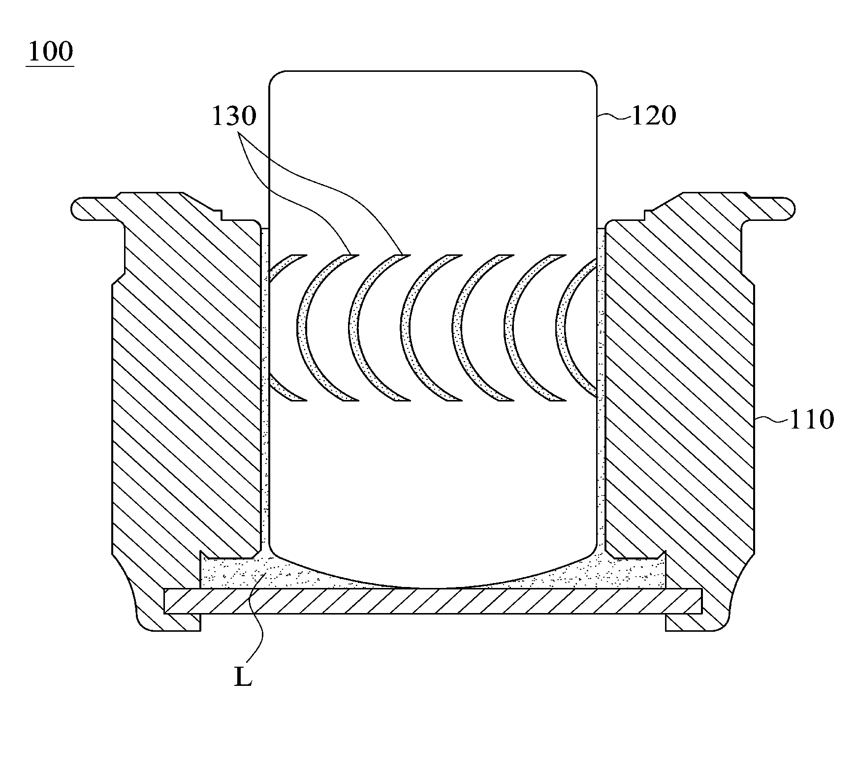
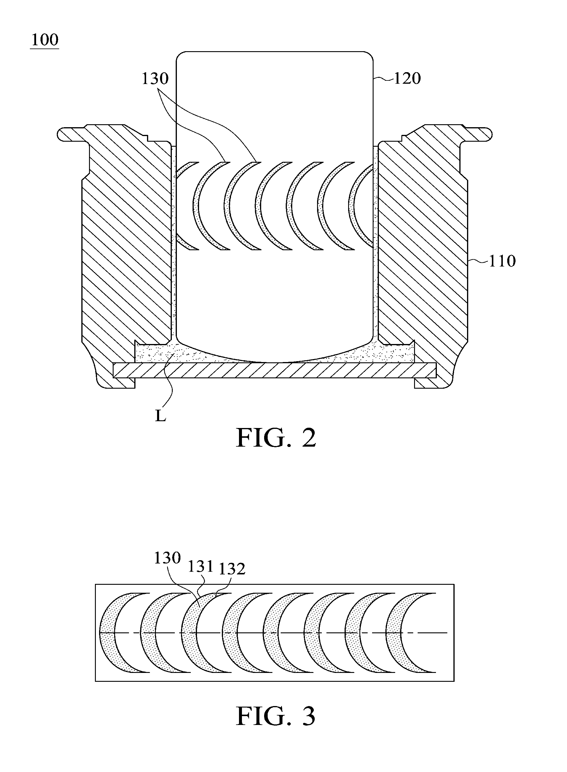
[0033]Referring to FIG. 2, a fluid dynamic bearing 100 comprises a sleeve 110, a shaft 120, and a plurality of elliptical grooves 130.

[0034]The shaft 120 is fit in the sleeve 110 and rotates with respect thereto. Specifically, the shaft 120 is fit in the sleeve 110 in an eccentric manner, and an outer surface of the shaft 120 is separated from an inner surface of the sleeve 110. Moreover, a lubricant L (such as lubrication oil) is filled between...


PUM


Abstract

A fluid dynamic bearing. A shaft is fit in the sleeve and rotates with respect thereto. A lubricant is filled between the shaft and the sleeve. At least one elliptical groove is formed on either the shaft or the sleeve and between the shaft and the sleeve. When the shaft rotates with respect to the sleeve, the lubricant is filled in the elliptical groove.

Description

CROSS REFERENCE TO RELATED APPLICATIONS[0001]This Application claims priority of Taiwan Patent Application No. 097133565, filed on Sep. 2, 2008, the entirety of which is incorporated by reference herein.BACKGROUND OF THE INVENTION[0002]1. Field of the Invention[0003]The invention relates to fluid dynamic bearings, and more particularly to fluid dynamic bearings with enhanced load capacity and anti-leak effects.[0004]2. Description of the Related Art[0005]Frictional loss, rotating noise, and reduced lifespan are conditions which relate to a ball bearing applied in a (spindle) motor of an electronic device. To overcome the aforementioned disadvantages, a fluid bearing containing a lubricant has been developed to replace the ball bearing applied in the (spindle) motor of the electronic device.[0006]For a fluid dynamic bearing, a lubricant is filled between a stationary sleeve and a shaft, preventing collision and abrasion during rotation of the shaft. Here, the shaft is fit in the slee...

Claims


Application Information

Patent Timeline
Patent Type & Authority Applications(United States)
IPC IPC(8): F16C32/06
CPCF16C17/026F16C32/06F16C33/107
Inventor YEN, RUEY-HORCHEN, CHIEN-YOU
Owner NAT TAIWAN UNIV
Learn More