
Base Station and Receiver Failure Diagnosing Method

a technology of base station and receiver, which is applied in the direction of transmission monitoring, substation equipment, wireless communication, etc., can solve the problems of difficult to receive a signal from an antenna, demodulate the signal, and increase the mounting area and power consumption, so as to achieve the effect of not deteriorating the performance of the receiver

Inactive Publication Date: 2010-03-04
HITACHI LTD
View PDF3 Cites 2 Cited by
  • Summary
  • Abstract
  • Description
  • Claims
  • Application Information

AI Technical Summary

Benefits of technology

[0011]Therefore, the invention has an object to provide a base station and a receiver failure diagnosing method that can perform failure detection of a receiver in a radio communication base station without interrupting any service and without deteriorating the performance of the receiver by using a simple method. Furthermore, the invention has another object to make a diagnosis of a receiver in a radio communication base station by a minimum circuit construction.
[0014]Through the above method, the receiver diagnosis of the radio communication base station can be performed without interrupting any service and keeping reception quality by using the minimum circuit construction.
[0015]According to a diagnosis method of this invention, in a wireless communication system including a radio communication base station having an antenna, a receiver for receiving signals (waves) from terminals through the antenna and a diagnosis function unit for diagnosing normality of the receiver, and radio terminals for communicating with the radio communication base station, all the radio terminals stop transmission of signals (waves) in synchronism with a specific timing, and a switch provided in a main signal passage of the receiver is switched from the antenna to a terminator during this stop period (silence period) to prevent external noise from being input to the receiver and diagnose normality of the receiver. Furthermore, the diagnosis is made at a specific period to diagnose the normality of the receiver of the base station.
[0025]According to the invention, it is possible to provide a base station and a receiver failure diagnosing method that can perform failure detection of a receiver in a radio communication base station without interrupting any service and without deteriorating the performance of the receiver by using a simple method. Furthermore, according to the invention, it is possible to make a diagnosis of a receiver in a radio communication base station by a minimum circuit construction.

Problems solved by technology

When some failure occurs in these radio communication base station, it is necessary to surely detect the failure concerned.
In addition, when failure detecting devices and circuits are designed in a large scale, the mount area and the power consumption increase and also the manufacturing cost price rises up.
The method disclosed in JP-A-2006-319616 can simply diagnose the receiver, however, it is difficult to receive a signal from an antenna and demodulate the signal during the period when the signal to be input to a demodulator is switched from a reception signal to thermal noise for diagnosis.
However, when the single branch operation is performed during the diagnosis of the receiver, the service is not interrupted, however, the reception quality cannot be maintained in some cases.
When the deterioration of the reception sensitivity is severer, the transmission power of the radio terminal increases in the 1×Evolution−Data Only (1×EV−DO) system or the Ultra Mobile Broadband (UMB) system which perform the Power Back Off (PBO) control, and thus there is a risk that the continuous talk time is reduced or call breaking or reduction of traffic occurs due to blow-up of power.

Method used


Image

  • Base Station and Receiver Failure Diagnosing Method
  • Base Station and Receiver Failure Diagnosing Method
  • Base Station and Receiver Failure Diagnosing Method

Examples


Embodiment Construction

[0034]A method of diagnosing a receiver of a radio communication base station without interrupting any service will be described in detail with reference to the drawings.

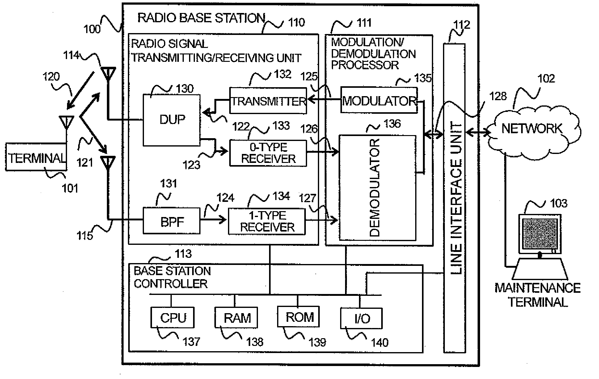
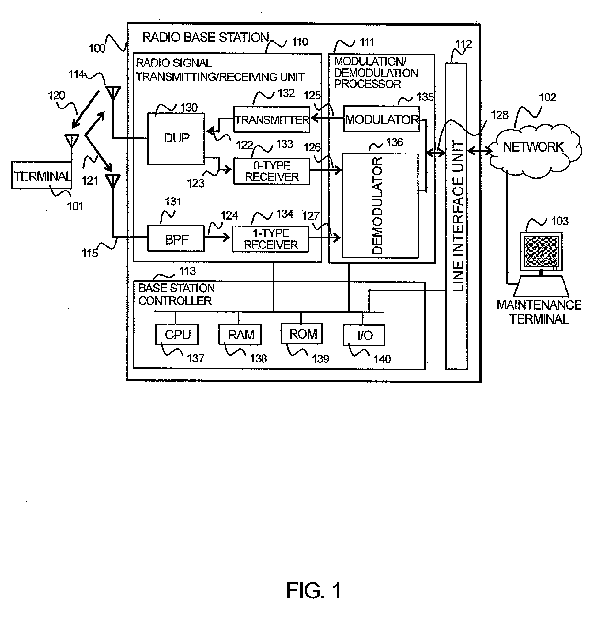
[0035]FIG. 1 is a diagram showing the construction of the radio base station.

[0036]An embodiment of the invention will be described by exemplifying a radio base station that has a transmitter of one system and receivers of two systems to enable diversity reception. The radio base station 100 comprises a radio signal transmitting / receiving unit 110, a modulation / demodulation processor 111, a line interface unit 112 and a base station controller 113. The radio signal transmitting / receiving unit 110 has a transmitter 132 of one system and receivers of two systems (0-type receiver 133 and 1-type receiver 134), and a 0-type antenna 114 shared to transmission and reception and a 1-type antenna 115 for reception are connected to the radio signal transmitting / receiving unit. Furthermore, the radio signal transmitting / receiv...


PUM


Abstract

A radio system has silence periods in which wave transmission from a terminal is stopped and in which a base station measures external noise power. The base station includes a receiver for receiving a signal from the terminal, and a controller that has preset frequency information representing a frequency of diagnosing the receiver to a measurement frequency of external noise power, and diagnoses normality of the receiver by using one silence period out of plural silence periods on the basis of the frequency information while measuring the external noise power by using the other silence periods. When the receiver is diagnosed, the external noise cannot be measured during this silence period, and thus during this silence period the external noise measured during the just preceding silence period is held and applied as external noise under the diagnosis of the receiver.

Description

CLAIM OF PRIORITY[0001]The present application claims priority from Japanese patent application JP 2008-223444 filed on Sep. 1, 2008, the content of which is hereby incorporated by reference into this application.BACKGROUND OF THE INVENTION[0002]1. Field of the Invention[0003]The present invention relates to a base station and a receiver failure diagnosing method, and particularly to a base station and a receiver failure diagnosing method in a radio communication system.[0004]2. Description of the Related Art[0005]System stability is one of important elements to put a mobile communication system into practice. In order to operate the system stably, it is required not only to prevent occurrence of any failure causing stop of the system operation, but also to quickly detect and restore an occurring failure. Accordingly, a failure detecting circuit and a diagnosing system thereof in a radio base station are very important.[0006]A transmitter and a receiver are mounted in a radio base s...

Claims


Application Information

Patent Timeline
Patent Type & Authority Applications(United States)
IPC IPC(8): H04W24/00
CPCH04W88/08H04W24/10
Inventor YASUMI, TATSUROFUJIWARA, KEI
Owner HITACHI LTD
Learn More