
Magnetic hinge assembly

Inactive Publication Date: 2010-03-11
HONG FU JIN PRECISION IND (SHENZHEN) CO LTD +1
View PDF9 Cites 58 Cited by
  • Summary
  • Abstract
  • Description
  • Claims
  • Application Information

AI Technical Summary

Problems solved by technology

However, the typical hinge assembly only includes two stable positions, so the cover only can be opened to two stable positions relative to the main body, and cannot remain in any other position.

Method used


Image

  • Magnetic hinge assembly
  • Magnetic hinge assembly
  • Magnetic hinge assembly

Examples


Embodiment Construction

[0016]The present magnetic hinge assembly may be used in foldable electronic devices, such as notebook computers, foldable mobile phones, media players, and so on.

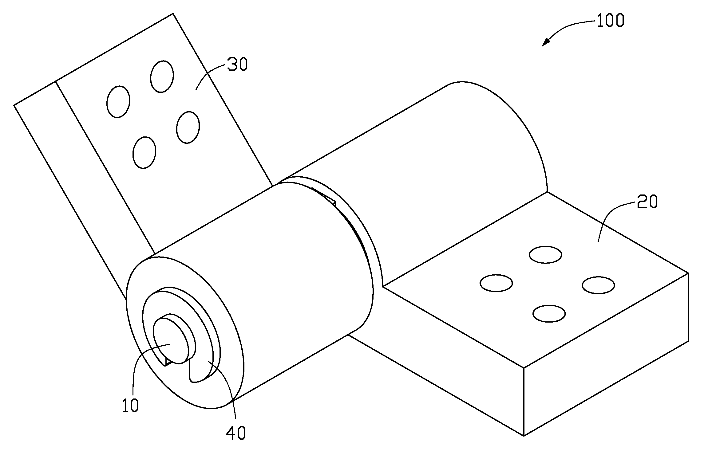
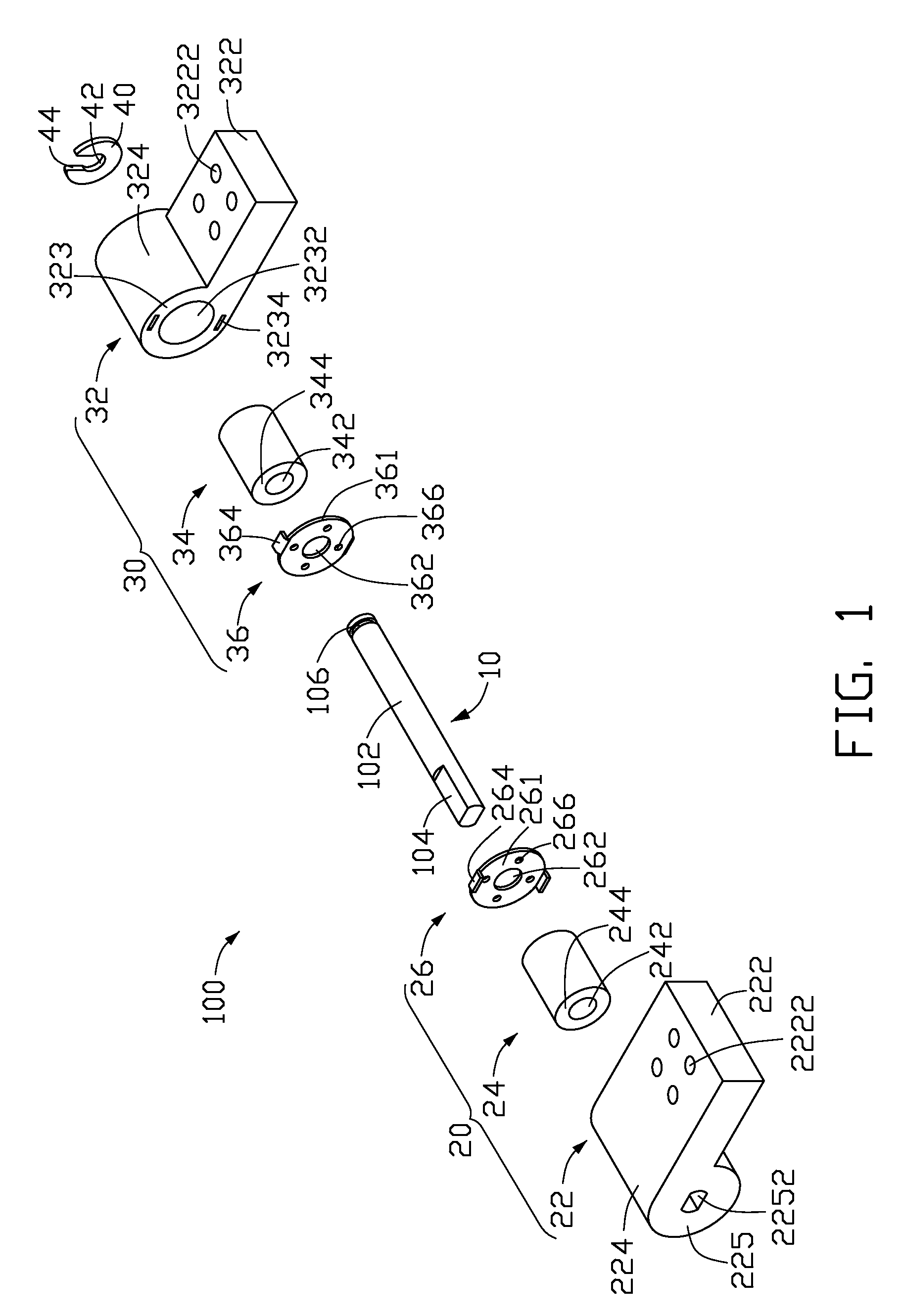
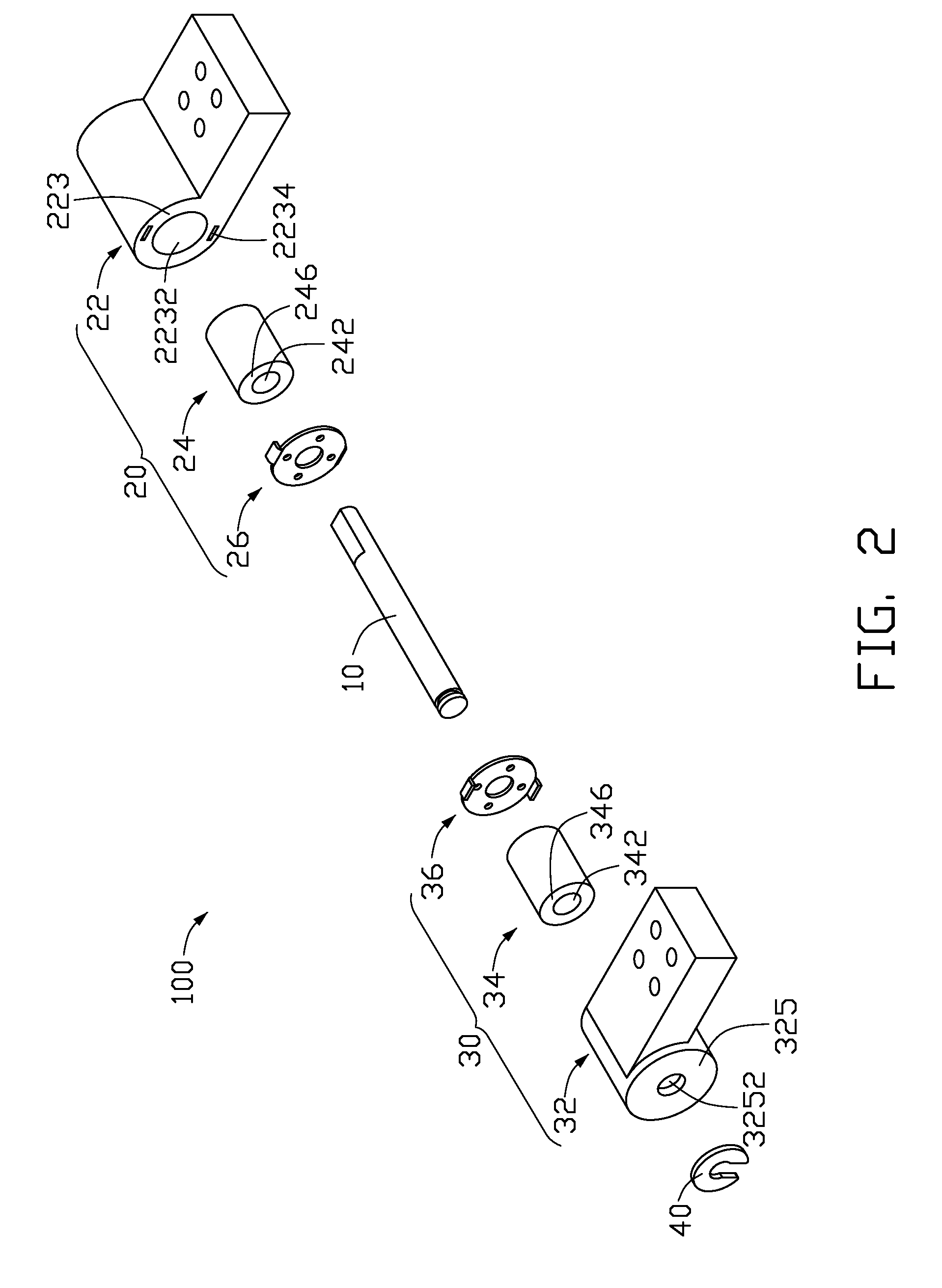
[0017]Referring to FIGS. 1 and 2, a first embodiment of a magnetic hinge assembly 100 includes a pivot shaft 10, a fixing module 20, a rotatable module 30, and a fixing member 40. The fixing module 20 is non-rotatably sleeved on the pivot shaft 10. The rotatable module 30 is rotatably sleeved on the pivot shaft 10. The fixing member 40 is fixed at an end of the pivot shaft 10.

[0018]The pivot shaft 10 includes a shaft portion 102 and a limiting portion 104 extending from a first end of the shaft portion 102, and defines a latching groove 106 around a second end of the shaft portion 102 opposite to the first end.

[0019]The fixing module 20 includes a fixing member 22, a first magnet 24, and a first friction member 26. The first magnet 24 is sleeved on the pivot shaft 10 and fixed in the fixing member 22. The first friction me...


PUM


Abstract

A hinge assembly includes a pivot shaft, a fixing module, a rotatable module, and a fixing member. The pivot shaft includes a first end and a second end opposite to the first end. The fixing module is non-rotatably sleeved on the pivot shaft adjacent to the first end and includes a first magnet. The rotatable module is rotatably sleeved on the pivot shaft adjacent to the second end and includes a second magnet. A polarity of the second magnet faces an opposite polarity of the first magnet such that the first and second magnets creating an attracting force. The rotatable module is pushed to tightly contact the fixing module by the attracting force such that a friction is created between the rotatable module and the fixing module to hold the rotatable module. The fixing member is fixed at the second end of the pivot shaft.

Description

BACKGROUND[0001]1. Field of the Invention[0002]The present disclosure generally relates to hinge assemblies and, particularly, to a magnetic hinge assembly used in a foldable electronic device having a top cover and a main body.[0003]2. Description of the Related Art[0004]Foldable electronic devices, such as notebook computers, are popular for their portability. In the foldable electronic device, a cover is rotatably connected to a main body via a hinge assembly. A typical hinge assembly may be a magnetic hinge assembly.[0005]The typical magnetic hinge assembly includes a housing fixed in the main body, a pivot shaft fixed to the cover, a first magnet, and a movable second magnet. The housing defines a chamber. The pivot shaft is rotatably received in the chamber. The first magnet is fixed in the chamber. The second magnet is rotatably received in the chamber and sleeved on the pivot shaft. A polarity of the second magnet faces an opposite polarity of the first magnet such that the ...

Claims


Application Information

Patent Timeline
Patent Type & Authority Applications(United States)
IPC IPC(8): E05D11/10
CPCG06F1/1616G06F1/1681Y10T16/5403Y10T16/5401H04M1/0216
Inventor WANG, JIN-XIN
Owner HONG FU JIN PRECISION IND (SHENZHEN) CO LTD
Features
  • Generate Ideas
  • Intellectual Property
  • Life Sciences
  • Materials
  • Tech Scout
  • Unparalleled Data Quality
  • Higher Quality Content
  • 60% Fewer Hallucinations
Learn More