Pilot Burner for Gas Turbine Engine

a technology of pilot burner and gas turbine engine, which is applied in the direction of machines/engines, mechanical equipment, lighting and heating apparatus, etc., can solve the problems of high levels of undesired combustion products

Inactive Publication Date: 2010-03-25
SIEMENS ENERGY INC
View PDF7 Cites 25 Cited by
  • Summary
  • Abstract
  • Description
  • Claims
  • Application Information

AI Technical Summary

Problems solved by technology

An undesired effect of the recirculation zone is the occurrence of regions of higher than average temperatur

Method used


Image

  • Pilot Burner for Gas Turbine Engine
  • Pilot Burner for Gas Turbine Engine
  • Pilot Burner for Gas Turbine Engine

Examples


Embodiment Construction

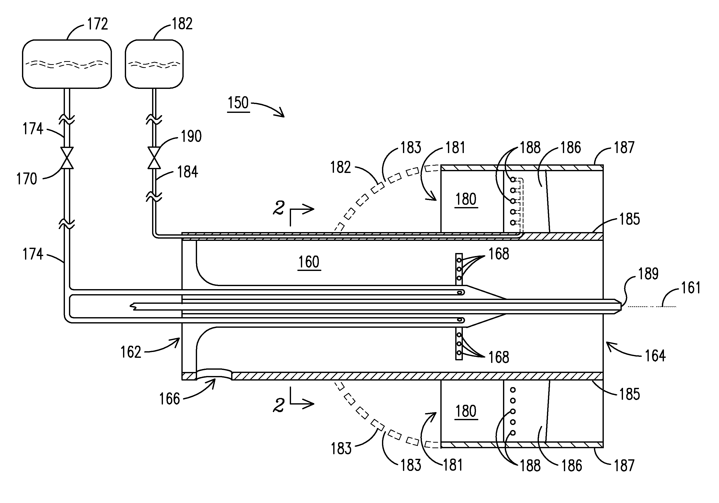
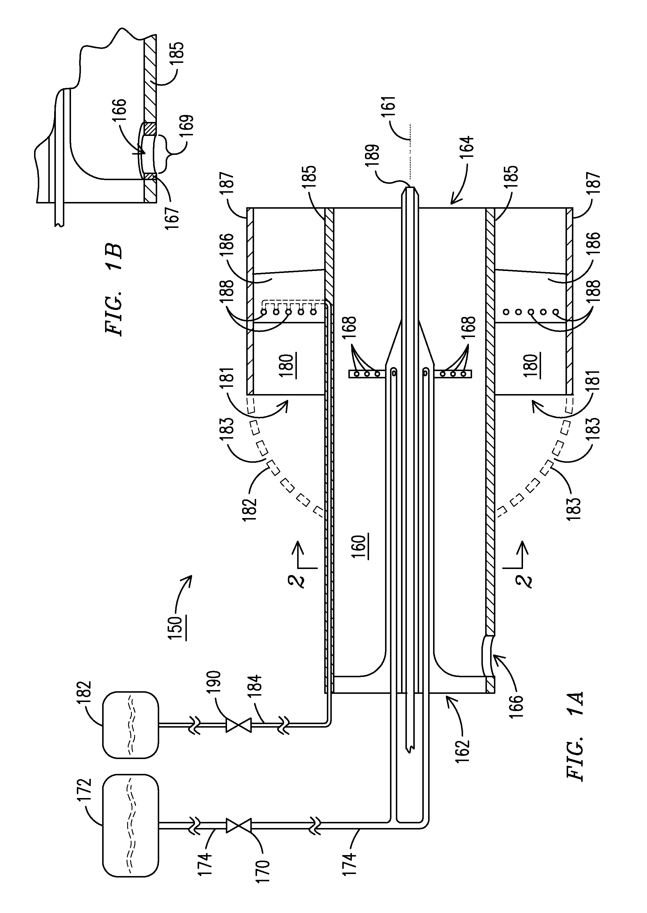
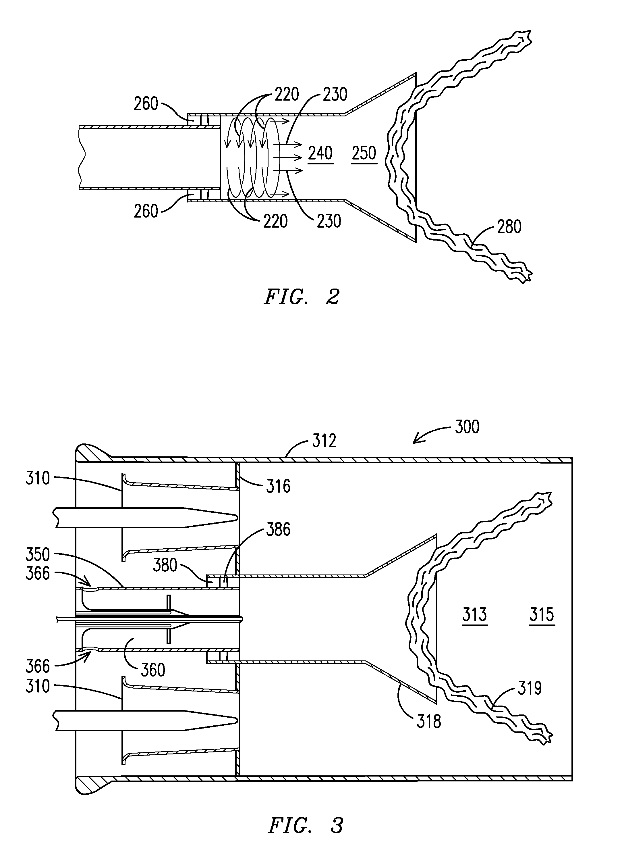
[0013]The present invention provides a flexible, superiorly controllable multi-passage pilot burner for gas turbine and other applications that may benefit from such pilot burner's low-NOx operation. To achieve this, various embodiments of the present invention include an inner and an outer mixing passage, each of these having separate inlets for a fluid oxidant, such as air, and separately controlled fuel outlets supplying fuel to the respective passages. The mixing of the fluid oxidant and fuel occurs in each respective mixing passage rather than at a common upstream locus. By providing for separate controls of fuel to each mixing passage, the pilot burners are considered to be fuel-profilable. Further, separate fluid oxidant flows are provided to the inner and outer mixing passages, and these flows may be modified in various embodiments through modifications at or near the entrances to the respective mixing passages to control flow velocity through the respective passage. Also, b...


PUM


Abstract

A pilot burner (150, 350) for a gas turbine engine delivers an inner non-swirling fuel-oxidant mixture surrounded by an outer swirling fuel-oxidant mixture, thereby providing enhanced mixing with no recirculation zone. At least one fluid-restricting inlet port (166, 366) provides an oxidant to an inner mixing passage (160, 360). The inner mixing passage (160, 360) includes a plurality of fuel outlets (168). An outer annular mixing passage (180) receives oxidant from an upstream port (181) surrounding the inner mixing passage and includes at least one swirler element (186, 386) and fuel outlets (188).

Description

FIELD OF INVENTION[0001]The invention generally relates to a gas turbine engine, and more particularly to a pilot burner capable of achieving low-NOx emissions during operation.BACKGROUND OF THE INVENTION[0002]Combustion engines such as gas turbine engines are machines that convert chemical energy stored in fuel into mechanical energy useful for generating electricity, producing thrust, or otherwise doing work. These engines typically include several cooperative sections that contribute in some way to this energy conversion process. In gas turbine engines, air discharged from a compressor section and fuel introduced from a fuel supply are mixed together and burned in a combustor section. The products of combustion are directed through a turbine section, where they expand and turn a central rotor.[0003]A variety of combustor designs exist, with different designs being selected for suitability with a given engine and to achieve desired performance characteristics. One popular combusto...

Claims


Application Information

Patent Timeline
IPC IPC(8): F23R3/28F23C7/00F23D11/00
CPCF23C2900/07001F23D2900/00008F23D2900/00015F23R2900/03343F23R3/14F23R3/286F23R3/343F23D2900/14701
Inventor MARTIN, SCOTT M.BLAND, ROBERT J.GULATI, ANIL
Owner SIEMENS ENERGY INC
Why Eureka
Try Eureka