Computer-processor based interface for telepresence system, method and computer program product

a computer-processor and telepresence technology, applied in the field of computer-processor-based interfaces for telepresence systems, methods and computer program products, can solve problems such as unnatural movements of participants, call launch may not result in a layout, and is almost impossible to control in current systems

Active Publication Date: 2010-03-25
CISCO TECH INC
View PDF6 Cites 233 Cited by
  • Summary
  • Abstract
  • Description
  • Claims
  • Application Information

AI Technical Summary

Benefits of technology

[0021]In yet another aspect, the GUI is a graphics-based controller for configuring the conference before the first connection is made. The configuration is optionally established through a telepresence server (TS) that coordinates the ultimate connections between telepresence systems, regardless if the TS is located at one of the systems or at a location that is different than any of the participating telepresence systems. This GUI allows unsophisticated users an easy and non-stressful way to establish the teleconference system configuration by having a visual display of how the users will be displayed in a simulated telepresence room before the conference takes place, allowing a relatively unsophisticated user to feel confident that they have properly prepared for the telepresence session before it starts. When a TS is used to make initial assignments of remote facilities to local displays, the user may subsequently change the assignments via the GUI, using a touchpanel display.

Problems solved by technology

This automatic call launch may not result in a layout as desired by the user.
This is almost impossible to control in current systems in an easy and user friendly way.
The eye-contact issue, and the feeling of participants from different sites being present in the same room is not fully resolved in conventional systems, as they capture the same picture and send the same to all the sites, thus making the movements of the participants look unnatural when they face a certain display (and associated camera) to talk to the participants displayed therein.
Furthermore, with these telepresence systems, there is no conventional mechanism for interconnecting different telepresence sites that are located on different networks.
Moreover, firewall traversal limits the ability to seamlessly establish connections between different telepresence sites.
Thus conventional telepresence systems have been restricted to dedicated, high-bandwidth communication lines.
Conventional telepresence systems are usually standalone systems that are not well integrated with other computer resources and video conference resources within a particular company's facilities.
Users of these telepresence systems are handicapped by having relatively limited amount of flexibility in adding other non-telepresence systems endpoints, and establishing calls between telepresence endpoints and other non-telepresence endpoints.
This makes for a frustrating experience for users not familiar with the telepresence system at hand, particularly when an urgent meeting is about to begin.

Method used


Image

  • Computer-processor based interface for telepresence system, method and computer program product
  • Computer-processor based interface for telepresence system, method and computer program product
  • Computer-processor based interface for telepresence system, method and computer program product

Examples


Embodiment Construction

[0043]Reference will now be made in detail to the present preferred embodiments of the invention, examples of which are illustrated in the accompanying drawings. Wherever possible, the same reference characters will be used throughout the drawings to refer to the same or like parts.

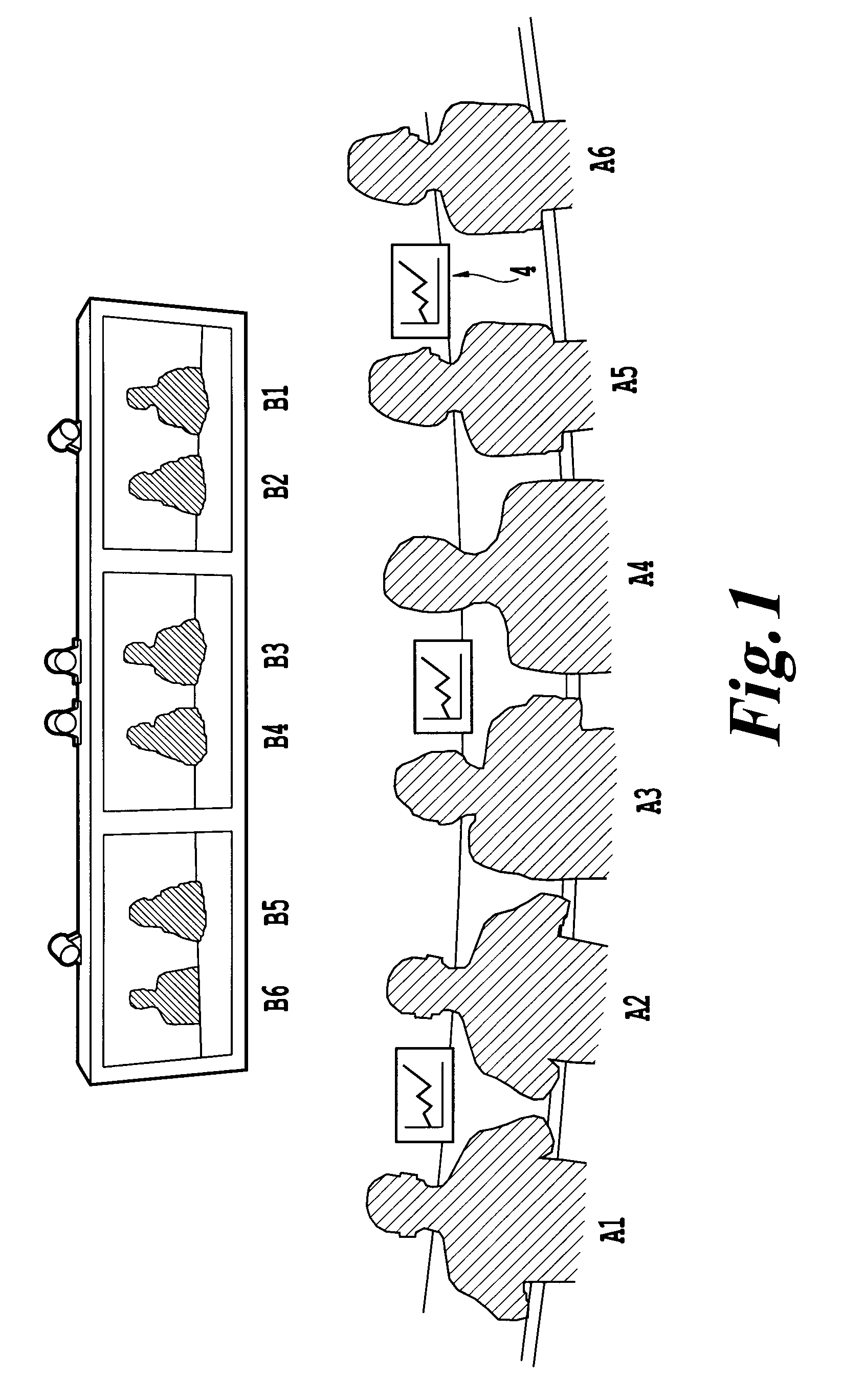
[0044]FIG. 1 shows a local telepresence video conferencing facility used by local participants (A1 to A6), which provides the local participants a feeling of actually being present in the same meeting-room as the remote participants (B1 to B6) that are shown on the respective displays (e.g., flat panel high resolution displays) 1, 2 and 3. As will be discussed in more detail, the users are provided with a tactile input device having a touchscreen display 4 (sometimes referred to as a combo display), which is mounted at an angle with respect to an upper surface of the table 4A on which they are mounted. The touchscreen displays 4 provide a tactile mechanism by which the local participants can provide input...


PUM


Abstract

A computer-implemented interface for a local telepresence video conferencing facility, pre-assigns displays at the local telepresence video conferencing facility to respective video images from remote telepresence video conference facilities such that respective video images from the remote telepresence video conference facilities will be displayed on corresponding displays at the local telepresence video conferencing facility once communications connections are made. A controller pre-assigns the displays according to control commands from a tactile input device prior to establishing the communication connections with the remote telepresence video conference facilities. A touchscreen display presents avatars of remote conference participants to illustrate pre-assignments of displays to particular remote telepresence video conference facilities prior to the communication connections being made.

Description

CROSS-REFERENCE TO RELATED APPLICATIONS[0001]The present non-provisional application claims priority from U.S. provisional application 61 / 097,779 filed on Sep. 17, 2008, the entire subject matter of which is incorporated herein by reference. Further, the present non-provisional application contains related subject matter to U.S. provisional application filed Mar. 16, 2007 and having Application Ser. No. 60 / 895,331, Norwegian patent application No. 20071401, filed on Mar. 16, 2007, U.S. provisional application Ser. No. 61 / 122,155 filed Dec. 12, 2008, and U.S. patent application Ser. No. 12 / 050,004, filed Mar. 17, 2008, the entire contents of all these documents being incorporated herein by reference.BACKGROUND[0002]1. Field of the Invention[0003]The present invention relates to a computer-processor based method and system for creating a dynamic interactive graphical user interface (GUI) for a videoconferencing system, method, and a computer program product having telepresence feature...

Claims


Application Information

Patent Timeline
Patent Type & Authority Applications(United States)
IPC IPC(8): H04N7/15G08B13/14G06F3/048G06F3/01G06F3/041G06F3/0486G06F3/0488
CPCG06F3/0486H04N7/152H04N7/147G06F3/04886
Inventor LOVHAUGEN, NORMAMELLINGEN, TORKEL STEFFENSHAW, EAMONN
Owner CISCO TECH INC
Why Eureka
Try Eureka