Connector connection terminal and connector using the same

a technology of connecting terminals and connectors, applied in the direction of connecting, electrical equipment, coupling devices, etc., can solve the problems of low holding strength and contact reliability of the connector connection terminal with respect to the base, the height of the connector connection terminal and the miniaturization of the same, and the difficulty of molds, etc., to achieve the effect of lowering the heigh

Inactive Publication Date: 2010-04-01
ORMON CORP
View PDF3 Cites 15 Cited by
  • Summary
  • Abstract
  • Description
  • Claims
  • Application Information

AI Technical Summary

Benefits of technology

[0009]One or more embodiments of the present invention provides a connector connection terminal having a lower height and being miniaturized while ensuring the desired holding strength and contact reliability.
[0011]According to one or more embodiments of the present invention, a slit is formed and cut out on the upper side of the fixed piece and the aspect ratio of the cross-sectional area of the elastic arm having a lower contact at the free end is greater than or equal to 1.2. Thus, the elastic arm is easily elastically deformed, and the holding strength is not lowered even if the fixed piece is inserted and fixed to the base. As a result, a connector connection terminal having a lowered height and being miniaturized while ensuring the desired contact reliability and holding strength is obtained.
[0013]According to one or more embodiments of the present invention, a slit having an optimum cross-sectional area is formed to cut out the elastic arm, and thus a connector connection terminal having a lowered height and being miniaturized while ensuring the desired contact reliability and holding strength is obtained.
[0015]According to one or more embodiments of the present invention, the bottom positioned on the lower side of the slit that cut out the elastic arm has an optimum cross-sectional area, and thus a connector connection terminal having a lowered height and being miniaturized while ensuring the desired contact reliability and holding strength is obtained.
[0017]According to one or more embodiments of the present invention, a connector capable of having a lowered height and being miniaturized while ensuring the desired holding strength and contact reliability is obtained.

Problems solved by technology

However, there is a limit to lowering the height of the connector connection terminal and miniaturizing the same since the connector connection terminal is normally manufactured by punching out the conductive thin plate through press working.
In particular, it is not easy to mold the fixed beam having a free end that curves to be smaller by press working, and even if molded, the holding strength and the contact reliability of the connector connection terminal with respect to the base are low.

Method used


Image

  • Connector connection terminal and connector using the same
  • Connector connection terminal and connector using the same
  • Connector connection terminal and connector using the same

Examples


Embodiment Construction

[0024]In embodiments of the invention, numerous specific details are set forth in order to provide a more thorough understanding of the invention. However, it will be apparent to one of ordinary skill in the art that the invention may be practiced without these specific details. In other instances, well-known features have not been described in detail to avoid obscuring the invention.

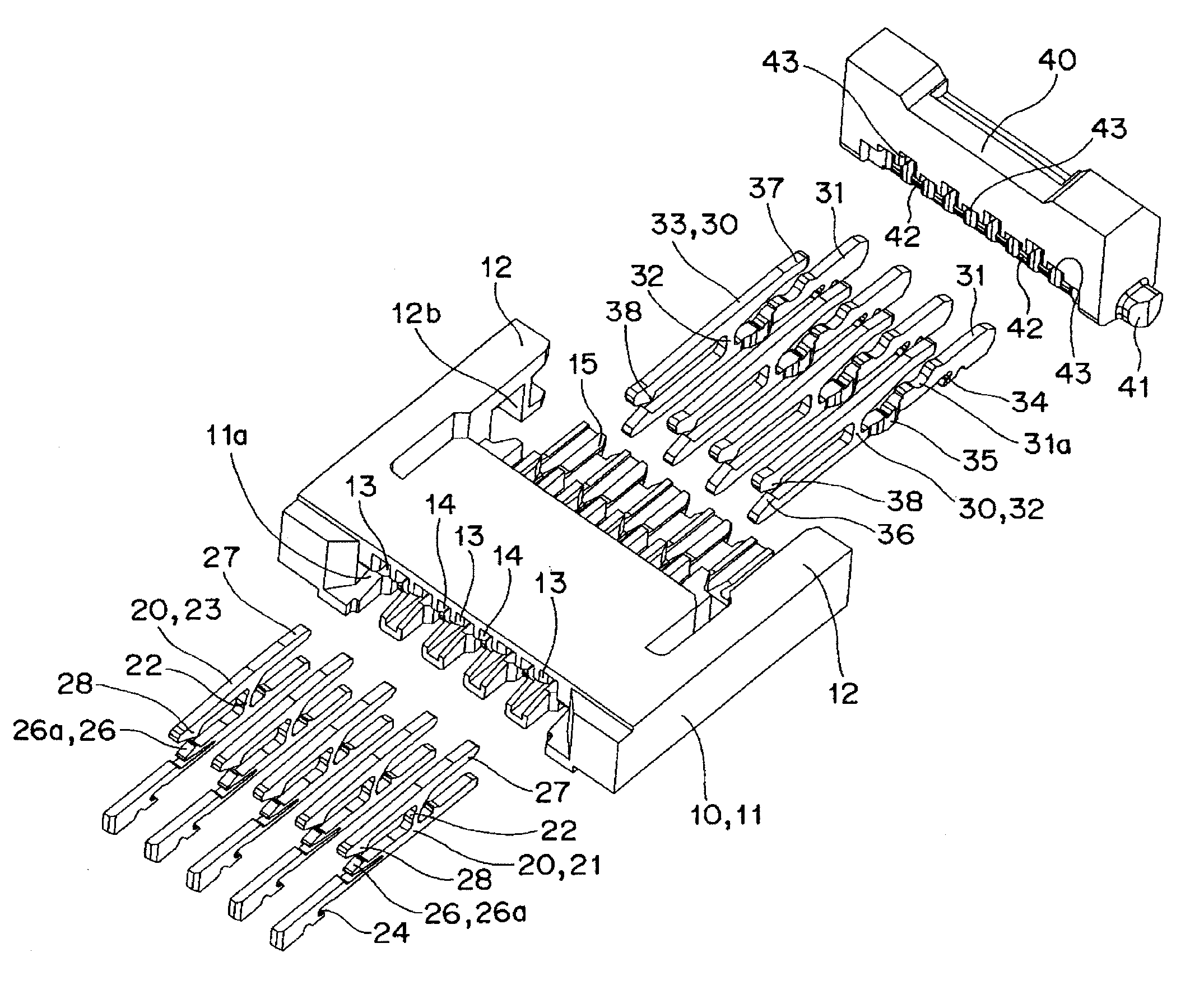
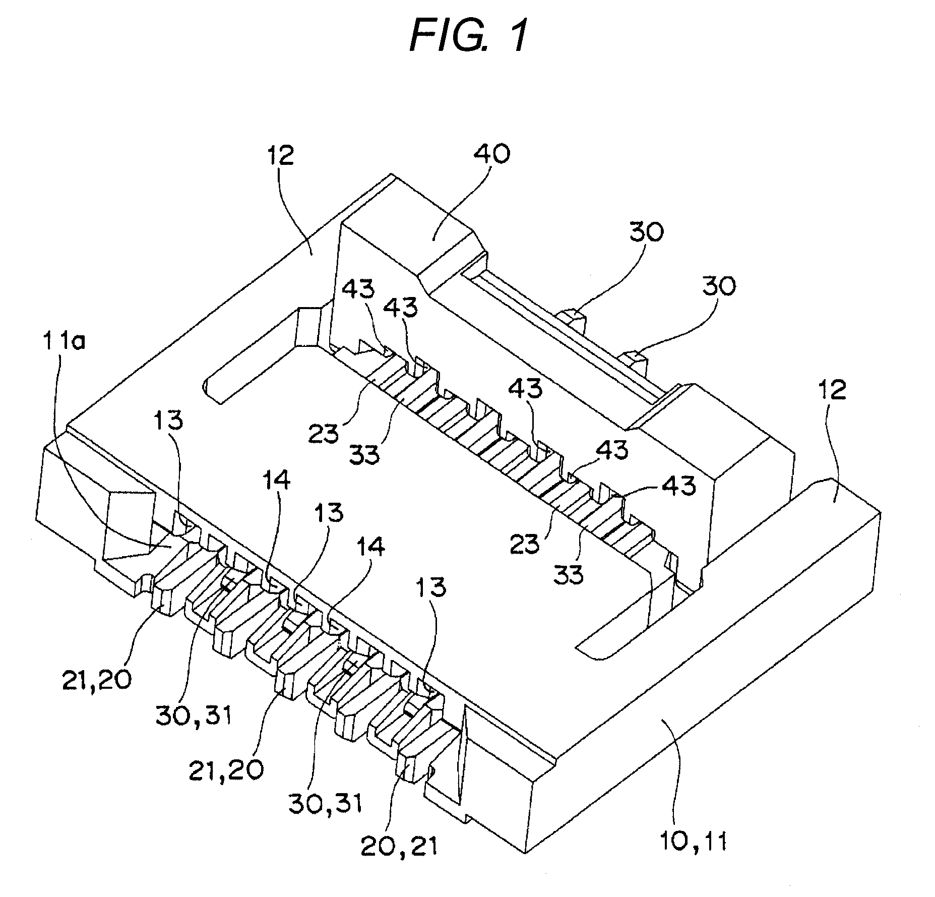
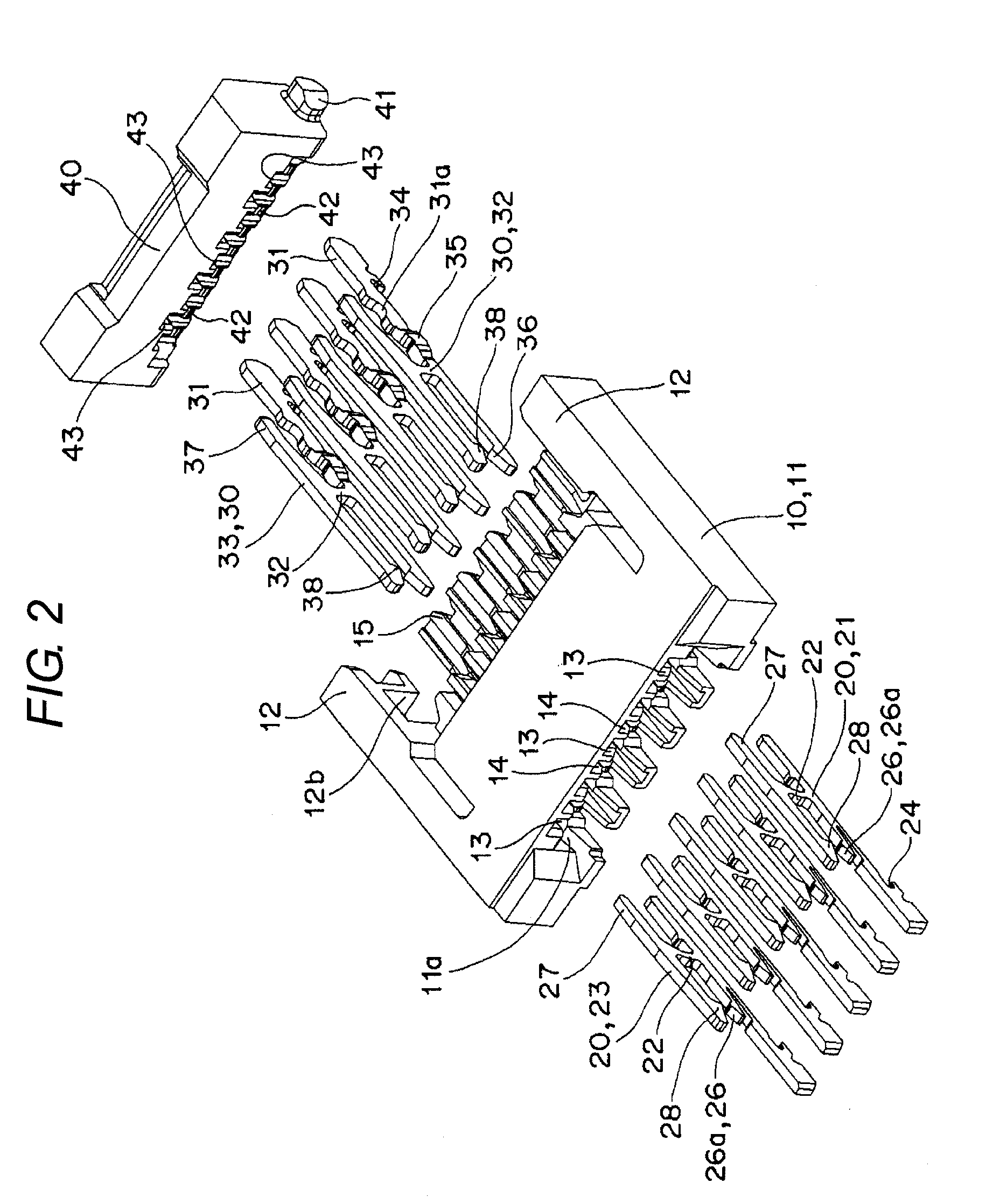
[0025]Hereinafter, an embodiment in which a connector connection terminal according to one or more embodiments of the present invention is incorporated in a connector will be described with reference to FIG. 1 to FIG. 5.

[0026]As shown in FIG. 1, the present embodiment is a case applied to a connector 10 for connecting a flexible print substrate (not shown). As shown in FIG. 2, the connector 10 broadly includes a base 11, a first connection terminal 20, a second connection terminal 30, and an operation lever 40.

[0027]The base 11 has elastic arms 12, 12 extending in parallel to the rear surface side from ...


PUM


Abstract

A connector connection terminal has a fixed piece to be inserted and fixed to a base of a connector, a coupling portion projecting out from an upper side of the fixed piece, and a movable piece extending along the fixed piece from an upper end of the coupling portion and having one end as an upper contact and another end acting as an operation receiving portion. A lower contact is arranged at a position facing the upper contact of the upper side of the fixed piece. The operation receiving portion of the movable piece is operated with an operation lever rotatably supported by the base. An elastic arm is cut out with a slit formed along the upper side of the fixed piece to define a free end of the elastic arm as a lower contact. An aspect ratio of a cross-sectional area of the elastic arm is greater than or equal to 1.2.

Description

BACKGROUND OF INVENTION[0001]1. Technical Field[0002]The present invention relates to connector connection terminals, and in particular, to a connection terminal incorporated in a connector for connecting a flexible print substrate.[0003]2. Related Art[0004]Conventionally, the connector connection terminal may be an electrical connector including a contact with a fixed beam and a movable beam extending along an inserting direction of a connection target, an insulating housing for interiorly holding the contact, and an actuator, positioned on the side opposite to the side of inserting the connection target, for elastically deforming the contact so as to come in contact with the connection target, the movable beam of the contact being supported in a freely oscillating manner by way of a coupling spring for joining the movable beam and the fixed beam, where the coupling spring has a shape extending in a curved manner towards a connector back end side or the direction the connection tar...

Claims


Application Information

Patent Timeline
Patent Type & Authority Applications(United States)
IPC IPC(8): H01R9/03
CPCH01R12/88H01R13/112H01R13/629H01R13/639H01R43/20
Inventor HEMMI, YOSHINOBUTERANISHI, HIROTADASAKASE, TADAYUKIKOYAMA, JIRO
Owner ORMON CORP
Why Eureka
Try Eureka