Differential power detection

Active Publication Date: 2010-04-08
HAMILTON SUNDSTRAND CORP
View PDF10 Cites 0 Cited by
  • Summary
  • Abstract
  • Description
  • Claims
  • Application Information

AI Technical Summary

Benefits of technology

[0014]A system for determining a differential power condition includes a first resistor electrically connected to a first input signal, a second resistor electrically connected to the first resistor and electrically connected to a second input signal, and a third resistor. The third resistor is electrically connected to the first resistor, the second resistor, and a common connection of the first input signal and the second input signal. A voltage across the third resistor is proportional to a difference between the first current and the second current. The system also includes a control module operable to determine a differential power condition in response to the voltage across the first resistor exceeding a first threshold, the difference between the first input signal and the second input signal exceeding a second threshold, or both.
[0015]A system for determining a differential power condition includes an electric generator associated with a turbine engine of an aircraft and a load. The load is coupled to the electric generator via a power bus. The system also includes a first transducer, a second transducer, and a circuit for detecting a differential power condition. The firs

Problems solved by technology

Certain conditions, such as chafing, age, or wear, can cause power bus faults, such as undesirable connections to an unintended conductor or return path.
Such faults divert power from the power bus causing the amount of power leaving the source to not be equal to the amount of power arriving at the load.
However, the reliability of a circuit using BITE is calculated over the period of time between BIT tests, which is often very brief.
However, a feasible, cost effective method of stimulating the resistor 38 of FIG. 1 is not known.

Method used


Image

  • Differential power detection
  • Differential power detection
  • Differential power detection

Examples


Embodiment Construction

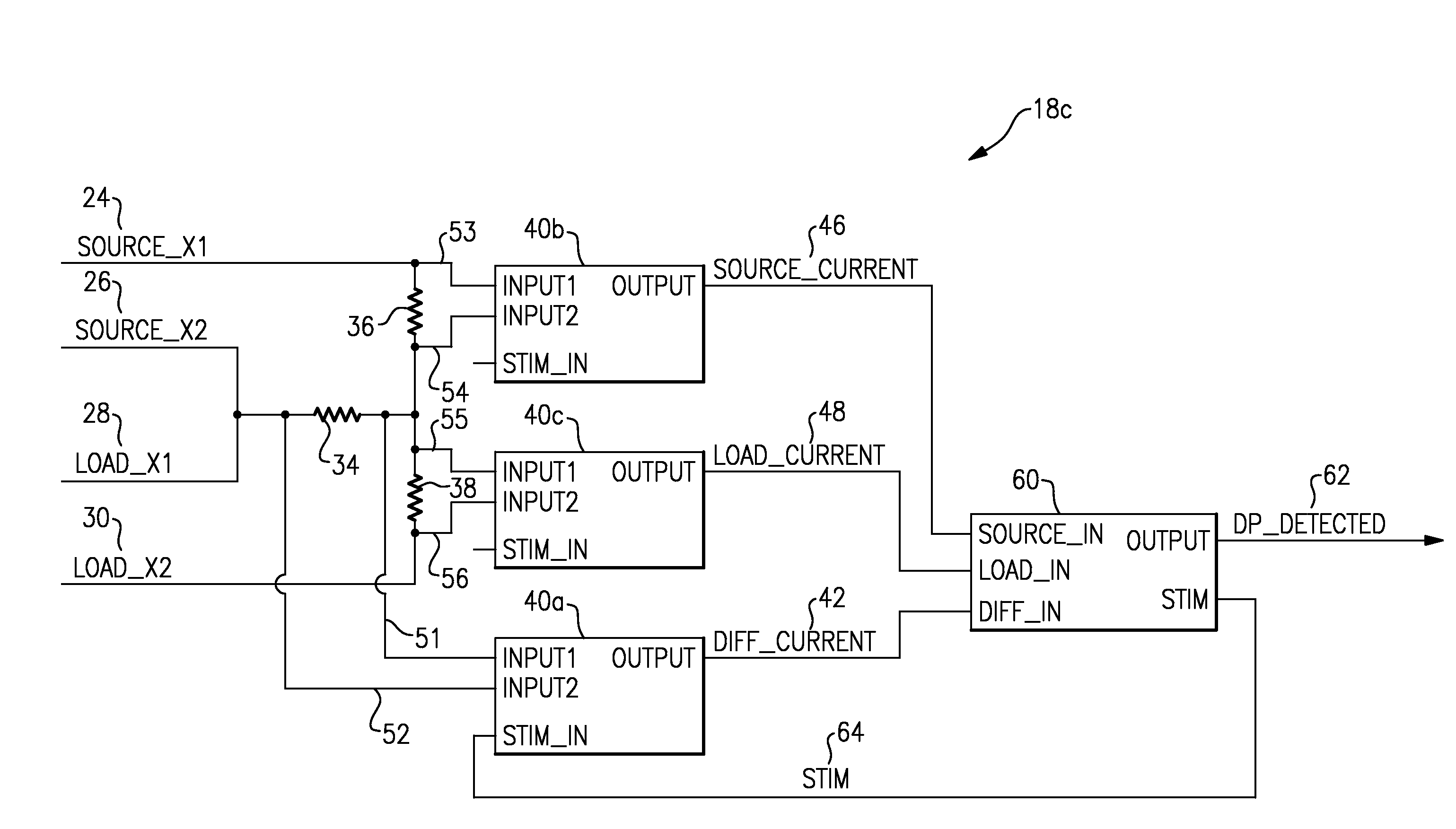
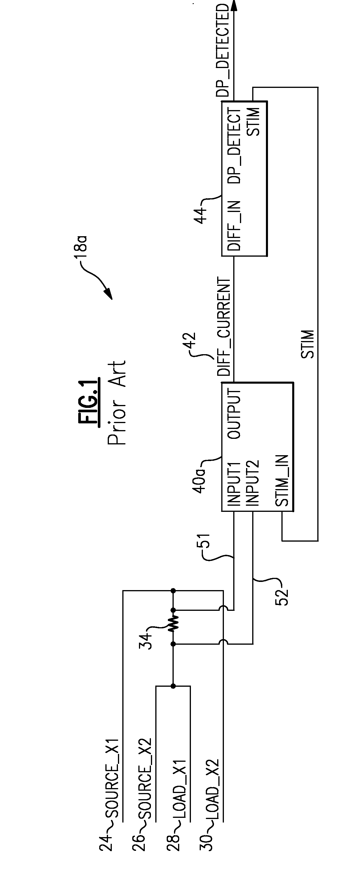
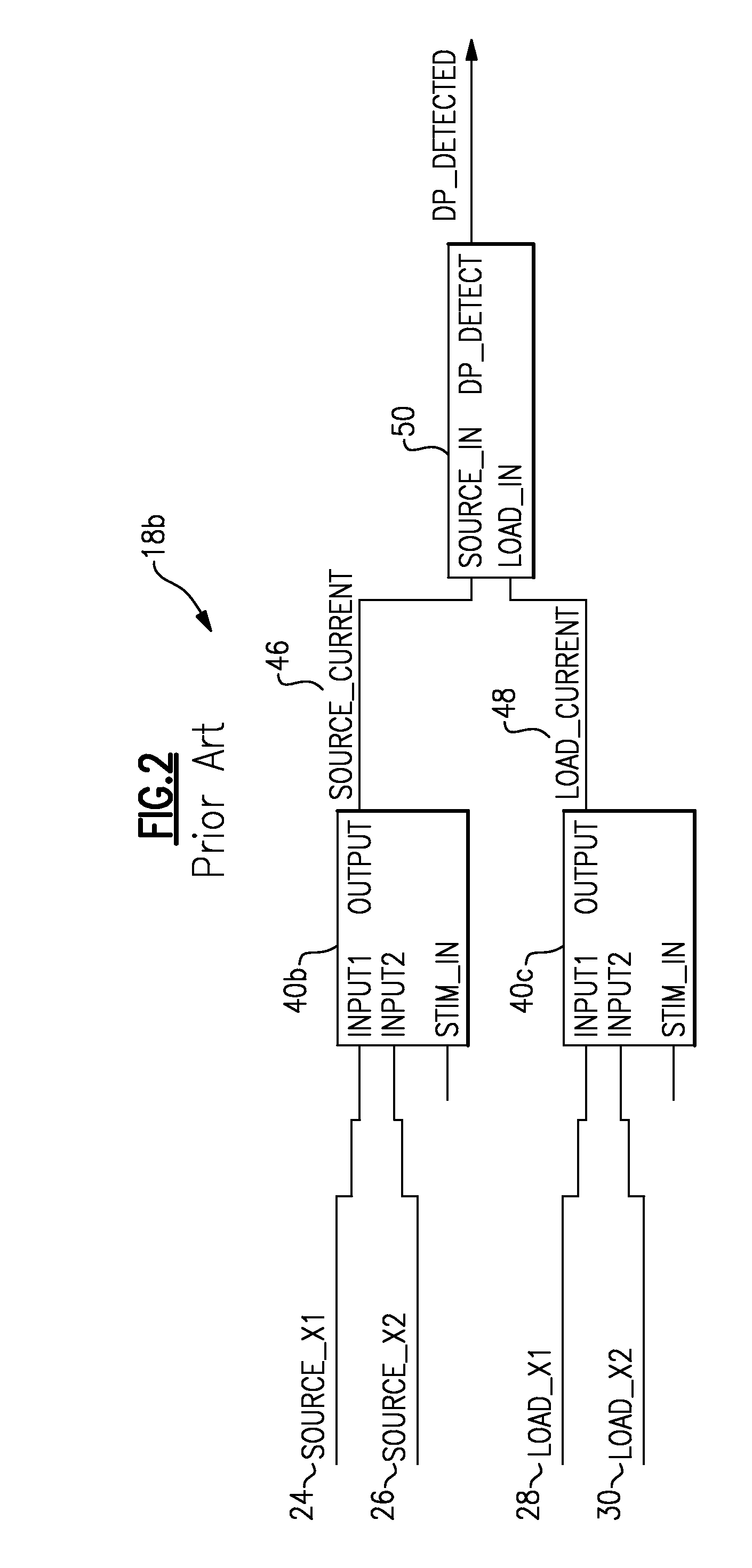
[0020]FIG. 3 schematically illustrates a system 10 that includes a power source 12, a load 14, and power bus 16 that conveys power from the power source 12 to the load 14. A first, source transducer 20 outputs a signal 24, 26 that is proportional to a current emanating from the power source 12 into the power bus 16 at a first location 17. A second, load transducer 22 outputs a signal 28, 30 that is proportional to the current flowing through the power bus 16 at a second location 19 into the load 14 (a “line current”). In one example the transducers 20, 22 are current transformers. The signal 24, 26 and the signal 28, 30 are current signals. Of course, other types and quantities of transducers could be used. The system 10 includes a circuit 18 that is operable to detect a differential power condition in response to the transducer signals 24, 26, 28, 30. In one example the system 10 corresponds to an aircraft, the source 12 corresponds to an electric generator associated with a turbin...


PUM


Abstract

A method of determining a differential power condition includes comparing a voltage across a resistor to a first threshold. The voltage across the resistor is proportional to a difference between a first current and a second current. The method also includes comparing a difference between the first current and the second current to a second threshold. A differential power condition is determined in response to the voltage across the resistor exceeding the first threshold, the difference exceeding the second threshold, or both.

Description

BACKGROUND OF THE INVENTION[0001]This application relates to power bus faults, and more specifically to a circuit operable to detect power bus faults.[0002]Power buses deliver power from a source to a load. Electrical power buses are conductors insulated from unintended conduction paths used to convey power from a source to a load. Certain conditions, such as chafing, age, or wear, can cause power bus faults, such as undesirable connections to an unintended conductor or return path. Such faults divert power from the power bus causing the amount of power leaving the source to not be equal to the amount of power arriving at the load. A method of detecting faults, called the “Differential Power” or “DP” method, detects a difference in power between source and load and, if the difference is excessive (exceeds a threshold), indicates a fault. The subject of this application is an improved method of implementing the “Differential Power” method of bus fault detection.[0003]The effectivenes...

Claims


Application Information

Patent Timeline
IPC IPC(8): G01R31/08
CPCH02H3/28
Inventor SCHMIDT, FREDERICK J.
Owner HAMILTON SUNDSTRAND CORP
Why Eureka
Try Eureka