Snap-off blade knife with safety stop

a blade knife and safety stop technology, applied in the direction of thrusting weapons, white arms/cold weapons, weapons, etc., can solve the problems of inadvertent and/or unintentional breakage of exposed segments

Inactive Publication Date: 2010-04-15
UNIVERSITY OF DELAWARE
View PDF50 Cites 23 Cited by
  • Summary
  • Abstract
  • Description
  • Claims
  • Application Information

AI Technical Summary

Problems solved by technology

With this design, however, more than one blade segment can be advanced from the blade handle at a time, which may in turn result in inadvertent and / or unintentional breakage of the exposed segments.

Method used


Image

  • Snap-off blade knife with safety stop
  • Snap-off blade knife with safety stop
  • Snap-off blade knife with safety stop

Examples


examples

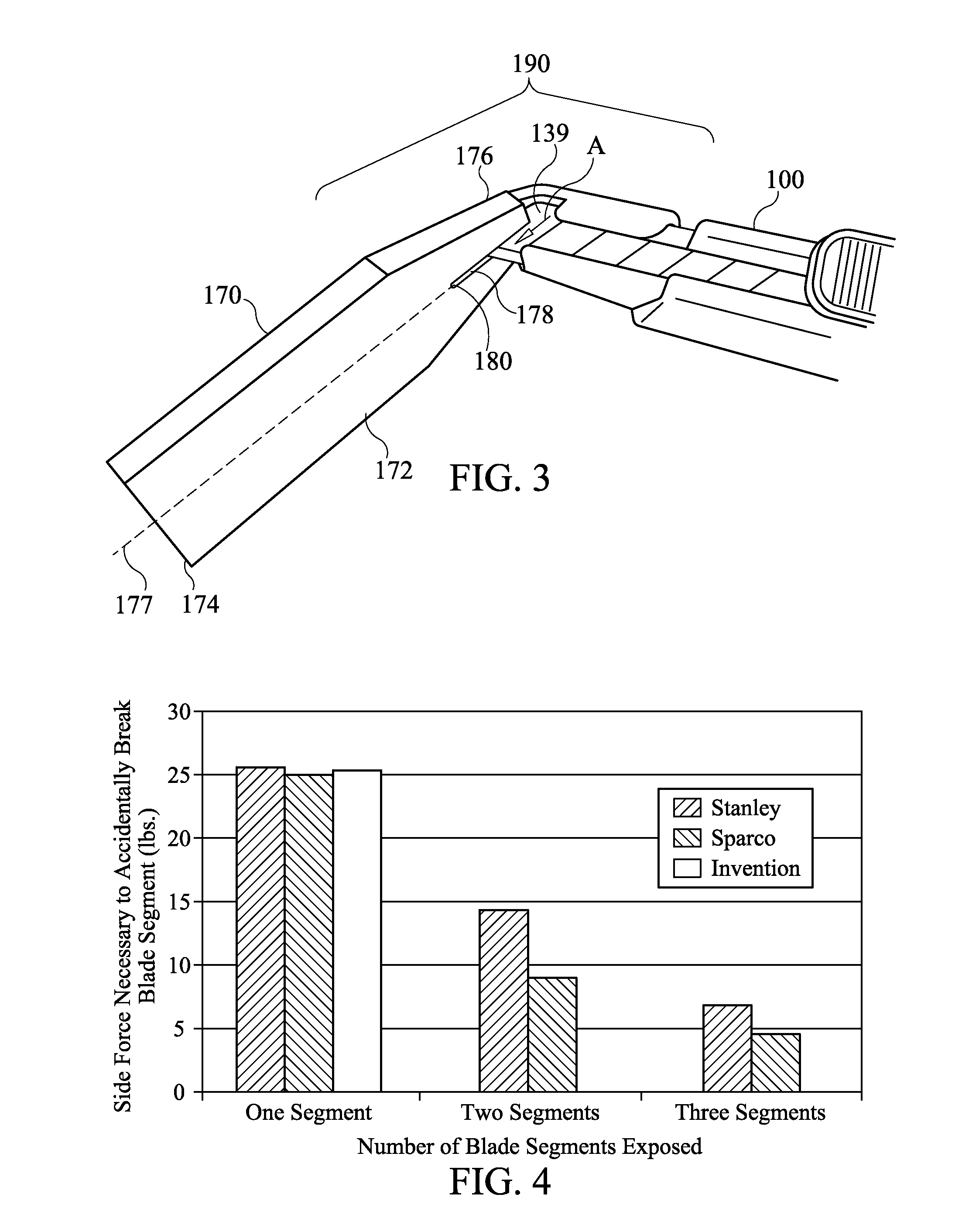
[0038]Mechanical testing has been conducted to determine an amount of force required to exert on a blade to cause a blade segment fracture. FIG. 4 illustrates side force required to break an exposed blade segment vs. number of blade segments exposed. A knife 100 and a segment blade snap-off tool 170 according to the exemplary embodiments described above, as well as two prior art snap-off blade knives (Prior Art 1 and Prior Art 2) were used in the testing.

[0039]For a single exposed blade segment using a knife 100 with a blade stop 150 according to an exemplary embodiment of the present invention or without using a blade stop according to two different embodiments of prior art knives, the measured force necessary to break the segment averaged about 25.5 pounds.

[0040]Because the knife according to the present invention does not allow as many as two blade segments to be exposed, the knife according to the present invention was not able to be used for tests with two or three exposed blad...


PUM


Abstract

A snap-off blade knife having a handle including a proximal portion, a distal portion, and a handle axis extending between the proximal portion and the distal portion is disclosed. The knife also includes a blade slidingly disposed within the handle along the handle axis. The blade comprises a plurality of scored segments. A blade stop fixedly extends from the distal portion of the handle. The blade stop includes a stop arm disposed to engage blade to limit extension of the blade from the handle. A kit comprising the snap-off knife and a blade segment snap-off tool is also disclosed.

Description

CROSS-REFERENCE TO RELATED APPLICATION[0001]This application claims priority to provisional application number U.S. 61 / 083,529, filed Jul. 25, 2008, which is incorporated herein, in its entirety, by reference.FIELD OF THE INVENTION[0002]The present invention provides a snap-off blade knife having a fixed feature that restricts the amount of the blade that may be extended from the knife handle.BACKGROUND OF THE INVENTION[0003]Commercially available snap-off blade knives, sometimes referred to as is box cutters, use a specially designed blade that includes several connected segments, each separated by a score line. This design allows a user to intentionally break off and discard dull segments, thus providing a new, sharp point or edge at the end of the knife blade. Once the dull segment has been removed, the blade may be advanced by the user to fully expose the new point and blade edge from the blade handle. With this design, however, more than one blade segment can be advanced from t...

Claims


Application Information

Patent Timeline
Patent Type & Authority Applications(United States)
IPC IPC(8): B26B1/08B26B5/00B26B29/02
CPCB26B29/00B26B5/002
Inventor GLANCEY, JAMES L.VINSON, JACK R.BRISACH, DANIEL
Owner UNIVERSITY OF DELAWARE
Why Eureka
Try Eureka