Equipment and method for manufacturing an optical fiber

a technology of optical fiber and manufacturing method, which is applied in the direction of manufacturing tools, furniture, lighting and heating apparatus, etc., can solve the problems of inability to form the core portion, inability to manufacture, and inability to manufacture,

Active Publication Date: 2010-04-22
SUMITOMO ELECTRIC IND LTD
View PDF2 Cites 5 Cited by
  • Summary
  • Abstract
  • Description
  • Claims
  • Application Information

AI Technical Summary

Benefits of technology

[0014]In addition, a method of manufacturing an optical fiber is provided as another embodiment of the invention. The method comprises: arranging a guide roller so as to intersect the advancing direction of the optical fiber, the guide roller being held by a roller supporting member so as to freely turn about an axial center X; oscillating the guide roller by driving the roller supporting member to revolve about the axial center Y, the axial center Y being inclined relative to the axis center X; and thereby causing the optical fiber to roll in contact with the surface of the guide roller so as to afford alternate twists to the optical fiber.

Problems solved by technology

It is difficult to form the core portion and the cladding portion in a perfectly circular and concentric shape in manufacturing an optical fiber.
These known mechanisms are complicated and the relevant equipment is inevitably large-sized.

Method used


Image

  • Equipment and method for manufacturing an optical fiber
  • Equipment and method for manufacturing an optical fiber
  • Equipment and method for manufacturing an optical fiber

Examples


first embodiment

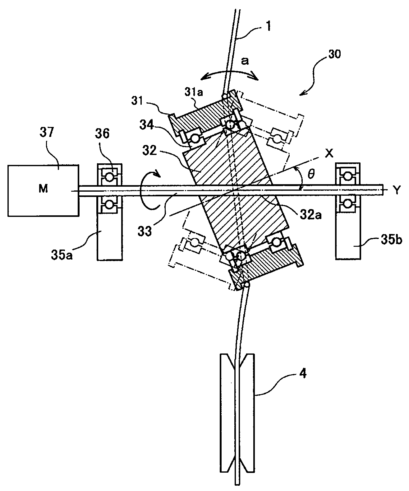
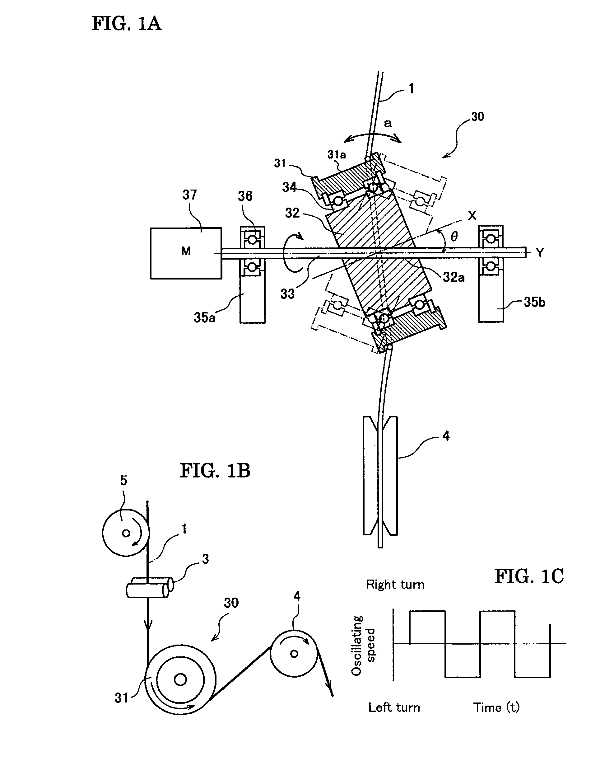
[0022]FIGS. 1A to 1C is are drawings for illustrating the oscillating mechanism of the guide roller in optical fiber manufacturing equipment according to the present invention, and FIG. 1A is a partial sectional view. An oscillating mechanism 30 comprises a guide roller 31 that is attached to a roller supporting member (support block) 32 through one pair of bearings 34 so as to be free to turn, the support block 32 being structured to rotate integrally with the rotating shaft 33. The rotating shaft 33 is supported at both ends by rotating-shaft supporting bodies 35a and 35b through shaft supports 36 composed of bearings. A drive motor 37 is combined to one end of the rotating shaft 33, so that the rotating shaft 33 and the support block 32 are turned in one direction at a given number of rotations.

[0023]The guide roller 31 freely turns around the support block 32, using the axial center X as its center. In the first embodiment, the axial center X has an inclination angle θ to the ax...

second embodiment

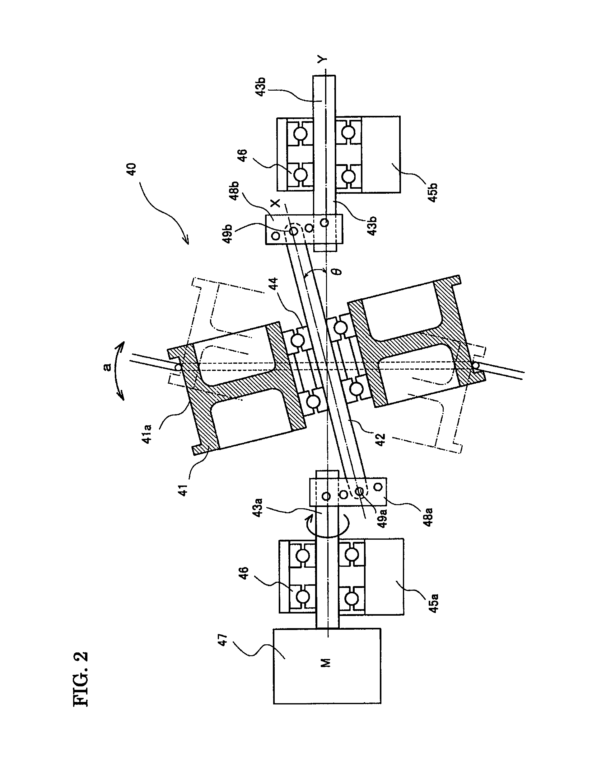
[0028]FIG. 2 is a partial sectional view illustrating an oscillating mechanism 40 of a guide roller in the optical fiber manufacturing equipment of the present invention. The oscillating mechanism 40 is an example of supporting a guide roller 41 so as to allowing its free rotation by using a roller supporting member (roller supporting shaft) 42 that is arranged to coincide with the axial center X of the guide roller 41. The roller supporting shaft 42 is connected at its both ends with rotating shafts 43a and 43b through angle adjusting members 48a and 48b, respectively, so as to be fixed to have a given angle θ to the rotating shaft 43a and 43b.

[0029]In the second embodiment, the roller supporting shaft 42 that supports the guide roller 41 is coincident with the axial center X of the guide roller 41, and not inclined like the rotating shaft 33 of the first embodiment. Thus, the guide roller 41 can be supported with one pair of small-diameter bearings 44. Supporting the guide roller...

third embodiment

[0033]FIG. 3 is a partial sectional view illustrating the oscillating mechanism 50 of a guide roller in the optical fiber manufacturing equipment of the present invention. In the oscillating mechanism 50, the guide roller 51 is supported through one pair of bearings 54 so as to be free to turn at a roller supporting member (support joint) 52. The support joint 52 is connected to one end of a rotating shaft 53 through a joint member 58 provided in its inside. The rotating shaft 53 is supported by a rotating-shaft supporting body 55 through a shaft support 56 composed of bearings. A drive motor 57 is combined with the other end of the rotating shaft 53, and the rotating shaft 53 is turned in one direction at a given number of rotations. In the oscillating mechanism 50, the guide roller is supported by cantilever and its oscillating angle is variable.

[0034]The guide roller 51 turns about the axial center X of the guide roller 51, freely revolving around the support joint 52. The suppor...


PUM

PropertyMeasurementUnit
angleaaaaaaaaaa
angleaaaaaaaaaa
angleaaaaaaaaaa

Abstract

Simple and small-sized equipment which continuously afford alternate twists to an optical fiber and a method using the apparatus are provided. The equipment includes: a guide roller for causing the fiber to roll; a roller supporting member for holding the roller in a manner allowing the roller to freely turn about an axial center X; and a driving unit to cause the roller to oscillate by making the supporting member to turn about an axial center Y that is inclined relative to the axial center X. The method includes: arranging a guide roller to intersect the fiber, the roller being held by a roller supporting member to freely turn about an axial center X; oscillating the roller by driving the supporting member to revolve about the axial center Y which is inclined relative to the axis center X; and causing the fiber to roll to afford alternate twists to the fiber.

Description

BACKGROUND OF THE INVENTION[0001]1. Field of the Invention[0002]The present invention relates to equipment and methods for manufacturing an optical fiber.[0003]2. Description of the Background Art[0004]It is difficult to form the core portion and the cladding portion in a perfectly circular and concentric shape in manufacturing an optical fiber. It is often the case that the core portion and the cladding portion become slightly ellipsoidal or distorted such that the cross-sectional refractive index profile of the optical fiber is not axial symmetry. As a result, the group velocities of mutually orthogonal two polarization modes that propagate in the optical fiber tend to differ from each other, and accordingly the polarization mode dispersion (PMD) increases. It is known that for manufacturing an optical fiber from an optical fiber preform, the drawing process is performed while affording twists to the optical fiber so that the PMD may be reduced.[0005]FIGS. 5A and 5B are drawings i...

Claims


Application Information

Patent Timeline
Patent Type & Authority Applications(United States)
IPC IPC(8): C03B37/01C03B37/03
CPCC03B37/032C03B37/02745
Inventor HABASAKI, TOSHIMITAKAGI, MITSURUABE, YUJIKASAI, HISASHI
Owner SUMITOMO ELECTRIC IND LTD
Why Eureka
Try Eureka