Equipment for providing twist to an optical fiber
a technology of optical fiber and twisting, which is applied in the direction of manufacturing tools, furniture, lighting and heating equipment, etc., can solve the problems of difficult to form the core portion, and inability to meet the requirements of the application
- Summary
- Abstract
- Description
- Claims
- Application Information
AI Technical Summary
Benefits of technology
Problems solved by technology
Method used
Image
Examples
first embodiment
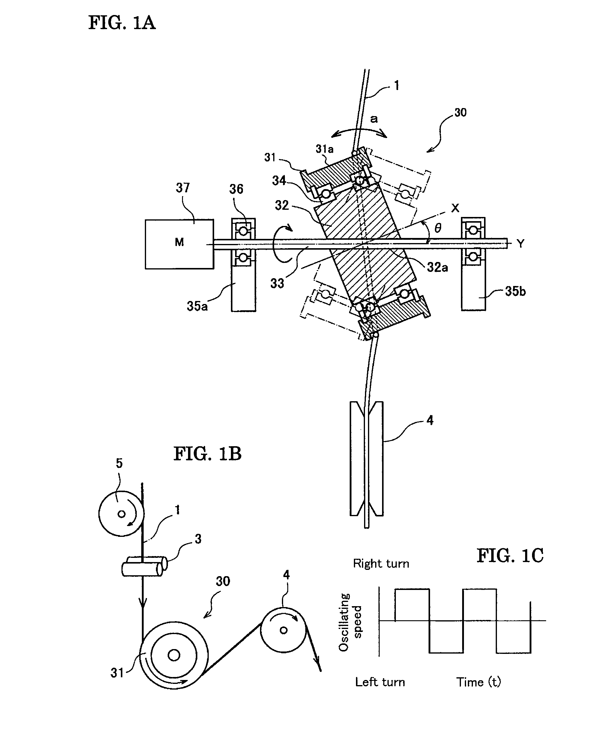
[0024]FIGS. 1A to 1C is are drawings for illustrating the oscillating mechanism of the guide roller in optical fiber manufacturing equipment according to the present invention, and FIG. 1A is a partial sectional view. An oscillating mechanism 30 comprises a guide roller 31 that is attached to a roller supporting member (support block) 32 through one pair of bearings 34 so as to be free to turn, the support block 32 being structured to rotate integrally with the rotating shaft 33. The rotating shaft 33 is supported at both ends by rotating-shaft supporting bodies 35a and 35b through shaft supports 36 composed of bearings. A drive motor 37 is combined to one end of the rotating shaft 33, so that the rotating shaft 33 and the support block 32 are turned in one direction at a given number of rotations.
[0025]The guide roller 31 freely turns around the support block 32, using the axial center X as its center. In the first embodiment, the axial center X has an inclination angle θ to the ax...
second embodiment
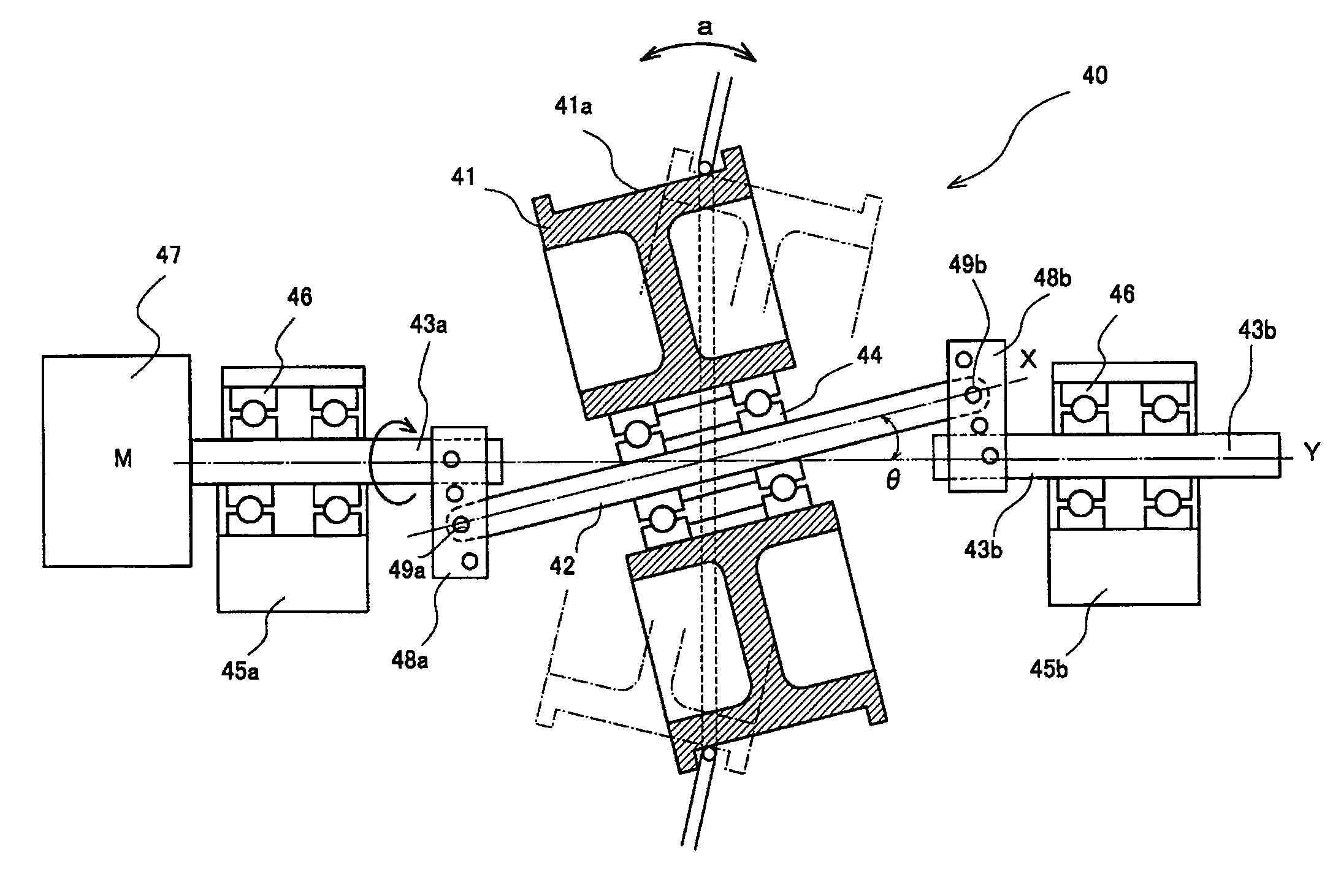
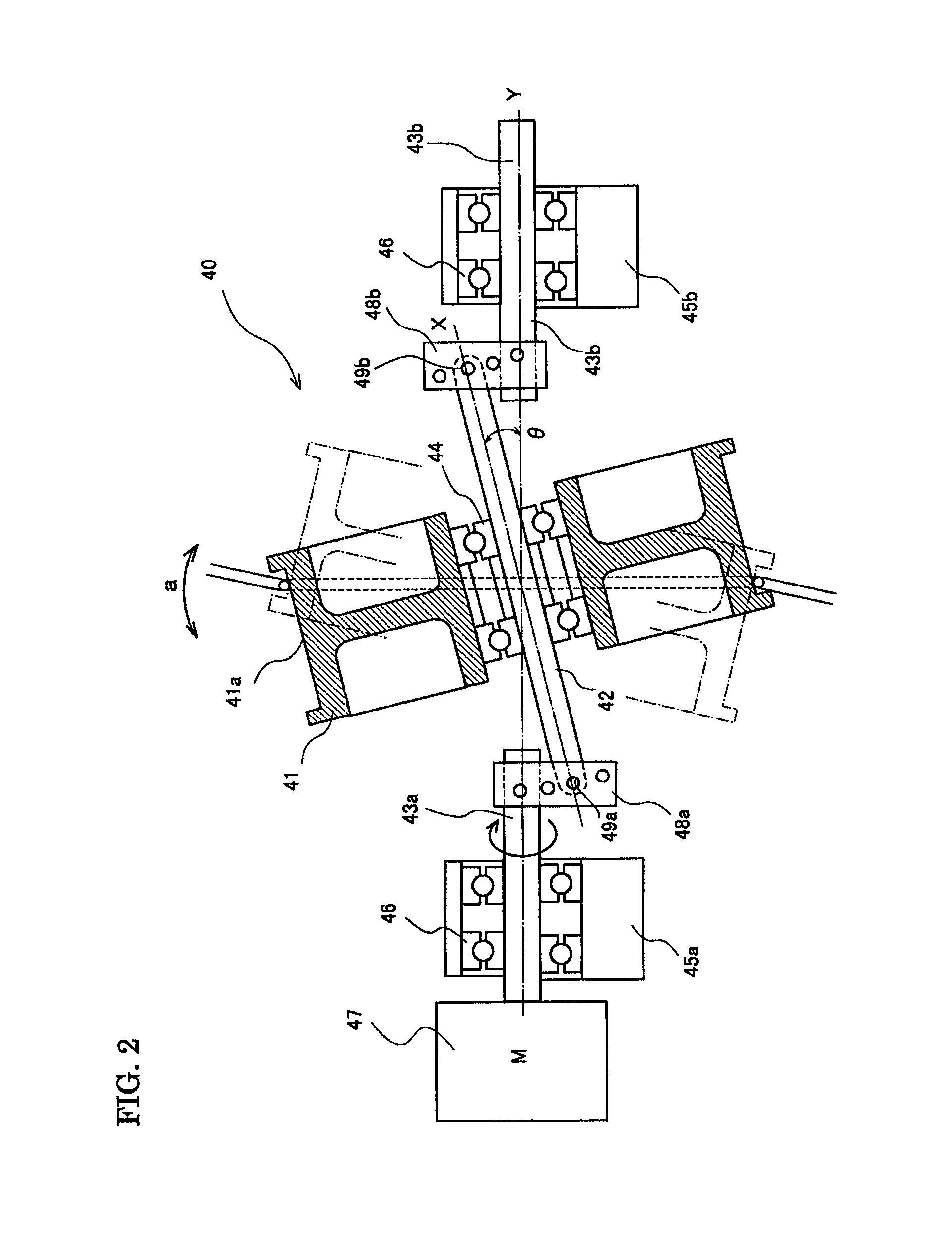
[0030]FIG. 2 is a partial sectional view illustrating an oscillating mechanism 40 of a guide roller in the optical fiber manufacturing equipment of the present invention. The oscillating mechanism 40 is an example of supporting a guide roller 41 so as to allowing its free rotation by using a roller supporting member (roller supporting shaft) 42 that is arranged to coincide with the axial center X of the guide roller 41. The roller supporting shaft 42 is connected at its both ends with rotating shafts 43a and 43b through angle adjusting members 48a and 48b, respectively, so as to be fixed to have a given angle θ to the rotating shaft 43a and 43b.
[0031]In the second embodiment, the roller supporting shaft 42 that supports the guide roller 41 is coincident with the axial center X of the guide roller 41, and not inclined like the rotating shaft 33 of the first embodiment. Thus, the guide roller 41 can be supported with one pair of small-diameter bearings 44. Supporting the guide roller...
third embodiment
[0035]FIG. 3 is a partial sectional view illustrating the oscillating mechanism 50 of a guide roller in the optical fiber manufacturing equipment of the present invention. In the oscillating mechanism 50, the guide roller 51 is supported through one pair of bearings 54 so as to be free to turn at a roller supporting member (support joint) 52. The support joint 52 is connected to one end of a rotating shaft 53 through a joint member 58 provided in its inside. The rotating shaft 53 is supported by a rotating-shaft supporting body 55 through a shaft support 56 composed of bearings. A drive motor 57 is combined with the other end of the rotating shaft 53, and the rotating shaft 53 is turned in one direction at a given number of rotations. In the oscillating mechanism 50, the guide roller is supported by cantilever and its oscillating angle is variable.
[0036]The guide roller 51 turns about the axial center X of the guide roller 51, freely revolving around the support joint 52. The suppor...
PUM
| Property | Measurement | Unit |
|---|---|---|
| angle | aaaaa | aaaaa |
| angle | aaaaa | aaaaa |
| angle | aaaaa | aaaaa |
Abstract
Description
Claims
Application Information
 - R&D
- Intellectual Property
- Life Sciences
- Materials
- Tech Scout
- Unparalleled Data Quality
- Higher Quality Content
- 60% Fewer Hallucinations
Browse by: Latest US Patents, China's latest patents, Technical Efficacy Thesaurus, Application Domain, Technology Topic, Popular Technical Reports.
© 2025 PatSnap. All rights reserved.Legal|Privacy policy|Modern Slavery Act Transparency Statement|Sitemap|About US| Contact US: help@patsnap.com


