Piezoelectric vibrating pieces, frames, and devices

Inactive Publication Date: 2010-04-22
NIHON DEMPA KOGYO CO LTD
View PDF7 Cites 11 Cited by
  • Summary
  • Abstract
  • Description
  • Claims
  • Application Information

AI Technical Summary

Benefits of technology

[0025]According to the present invention, piezoelectric vibrating pieces, piezoelectric frames, and piezoelectric devices are provi

Problems solved by technology

Also, with reduced arm length and width, the rigidity of the piezoelectric vibrating piece may degrade and become unable to withstand a dropping impact.
Increasing the pulling sensitivity increases the sensitivity of frequency variability, which makes it difficult to adjust the vibration frequency of 32.768 kHz, which is the objective frequency.
The grooves formed on the vibrating arms of a piezoelectric vibrating piece according to the '251 reference present certain limitations for use in miniaturized configurations of a piezoelectric vibrating piece.
Consequently, the CI value is undesirably increased.
However, fabrication steps for forming such a configuration become excessively difficult as the piezoelectric vibrating piece

Method used


Image

  • Piezoelectric vibrating pieces, frames, and devices
  • Piezoelectric vibrating pieces, frames, and devices
  • Piezoelectric vibrating pieces, frames, and devices

Examples


first embodiment

of Tuning-Fork Type Piezoelectric Vibrating Piece

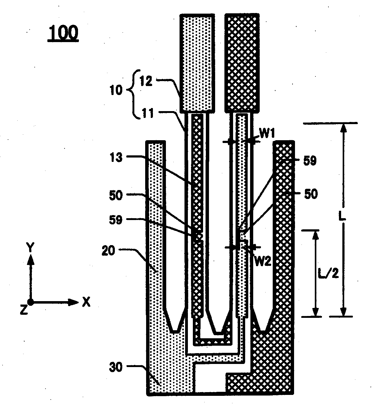
[0043]FIG. 1 is a plan view of this embodiment 100 of a tuning-fork type piezoelectric vibrating piece. This embodiment comprises a pair of vibrating arms 10 extending in the Y-axis direction (which is a designated longitudinal direction), a base 30 made of a piezoelectric material and formed continuously with the vibrating arms 10. In this embodiment the length of each vibrating arm 10 is about 1.25 mm and the length of the base is about 0.15 mm. The width (in the X-axis direction) of each vibrating arm 10 is 55 μm. This embodiment also comprises a pair of supporting arms 20 extending in the Y-axis direction. The supporting arms 20 are situated outboard of the respective vibrating arms.

[0044]The vibrating arms 10 extend in the Y-axis direction from the base 30. On each vibrating arm 10 a respective groove 13 is formed on the upper surface (visible in drawing) and a respective groove 14 (not visible in drawing) is formed on the lower ...

second embodiment

of Tuning-Fork Type Piezoelectric Vibrating Piece

[0056]The piezoelectric tuning-fork type vibrating piece 110 according to this embodiment is shown in FIG. 4. The piece 110 has substantially the same configuration as of the first embodiment 100 except for the configuration of the rib feature 51. The rib feature 51 is described below, but other detail being the same as in the first embodiment are not described further.

[0057]A respective rib feature 51 is situated in each groove 13, 14. In each groove, the rib features 51 extend from each of the +X and −X walls of the groove, and the respective rib features51 extend toward each other in the groove. That is, the rib features 51 in the groove form an opening 59 that is narrower than the respective groove 13.

[0058]As FIG. 4 shows, the length of a groove 13, 14 is denoted L. In this embodiment the rib feature 51 is situated at a distance 3 / L from the base toward the distal end of the groove. That is, the position of the rib feature 51 is ...

third embodiment

of Tuning-Fork Type Piezoelectric Vibrating Piece

[0068]FIG. 8 is a plan view of a third embodiment 120 of a tuning-fork type piezoelectric vibrating piece. The piece 120 has substantially the same configuration as the first embodiment 100, except for the rib feature 52. Thus, the rib feature 52 is described below in detail while omitting supererogatory descriptions of the other features.

[0069]FIG. 8 shows that, in this embodiment 120, a respective rib feature 52 is situated in each groove 13, 14 (grooves 14 not shown because they are on the under-surface of the vibrating arms). Thus, each groove on the upper surface and each groove on the lower surface has a respective rib feature. As depicted in the figure, the rib feature 52 in one of the grooves 13 extends from the +X wall of the groove, and the rib feature in the other of the grooves 13 extends from the −X wall of the groove. The ribs 52 are configured similarly in the grooves 14 on the under surface.

[0070]The width of each rib ...


PUM


Abstract

Piezoelectric vibrating pieces are disclosed that have a base and a pair of vibrating arms extending from one end of the base in a designated direction. A respective groove is defined in each of the upper and lower surfaces of each vibrating arm. The grooves extend in the designated direction and have a first width. Each groove includes a respective rib feature having a second width that is narrower than the first width. A piezoelectric frame includes the piezoelectric device and an outer frame surrounding the device. A piezoelectric device includes the piezoelectric vibrating piece or piezoelectric frame, a lid, and a base.

Description

CROSS-REFERENCE TO RELATED APPLICATION [0001]This application claims priority to and the benefit of Japan Patent Application No. 2008-267807, filed on Oct. 16, 2008, in the Japan Patent Office, the disclosure of which is incorporated herein by reference in its entirety.FIELD [0002]This disclosure relates to piezoelectric vibrating pieces, piezoelectric frames, and piezoelectric devices comprising the piezoelectric vibrating pieces and piezoelectric frames. More specifically, the disclosure pertains to piezoelectric vibrating pieces, frames, and devices that efficiently suppress unwanted increases of CI and have high rigidity as well as pulling sensitivity despite being miniaturized.DESCRIPTION OF THE RELATED ART [0003]For small information devices, such as HDDs (Hard Disc Drives), mobile computers, or IC cards, or clock sources for mobile phones, piezoelectric devices such as a piezoelectric vibrating piece or a piezoelectric oscillator are used. Especially nowadays, piezoelectric v...

Claims


Application Information

Patent Timeline
IPC IPC(8): H01L41/00H01L41/09H01L41/18H03H9/19H03H9/215
CPCH03H9/1014H03H9/21H03H9/1035
Inventor KAWANISHI, SHINGOYOSHIMATSU, MASAHIRO
Owner NIHON DEMPA KOGYO CO LTD
Why Eureka
Try Eureka