Spring-mounted vibration system to reduce vibration
a vibration system and spring technology, applied in the direction of machine supports, seating furniture, domestic objects, etc., can solve the problems of requiring replacement of springs and/or dampers, requiring high production and maintenance costs, and mounting vibration systems
- Summary
- Abstract
- Description
- Claims
- Application Information
AI Technical Summary
Benefits of technology
Problems solved by technology
Method used
Image

Examples
first embodiment
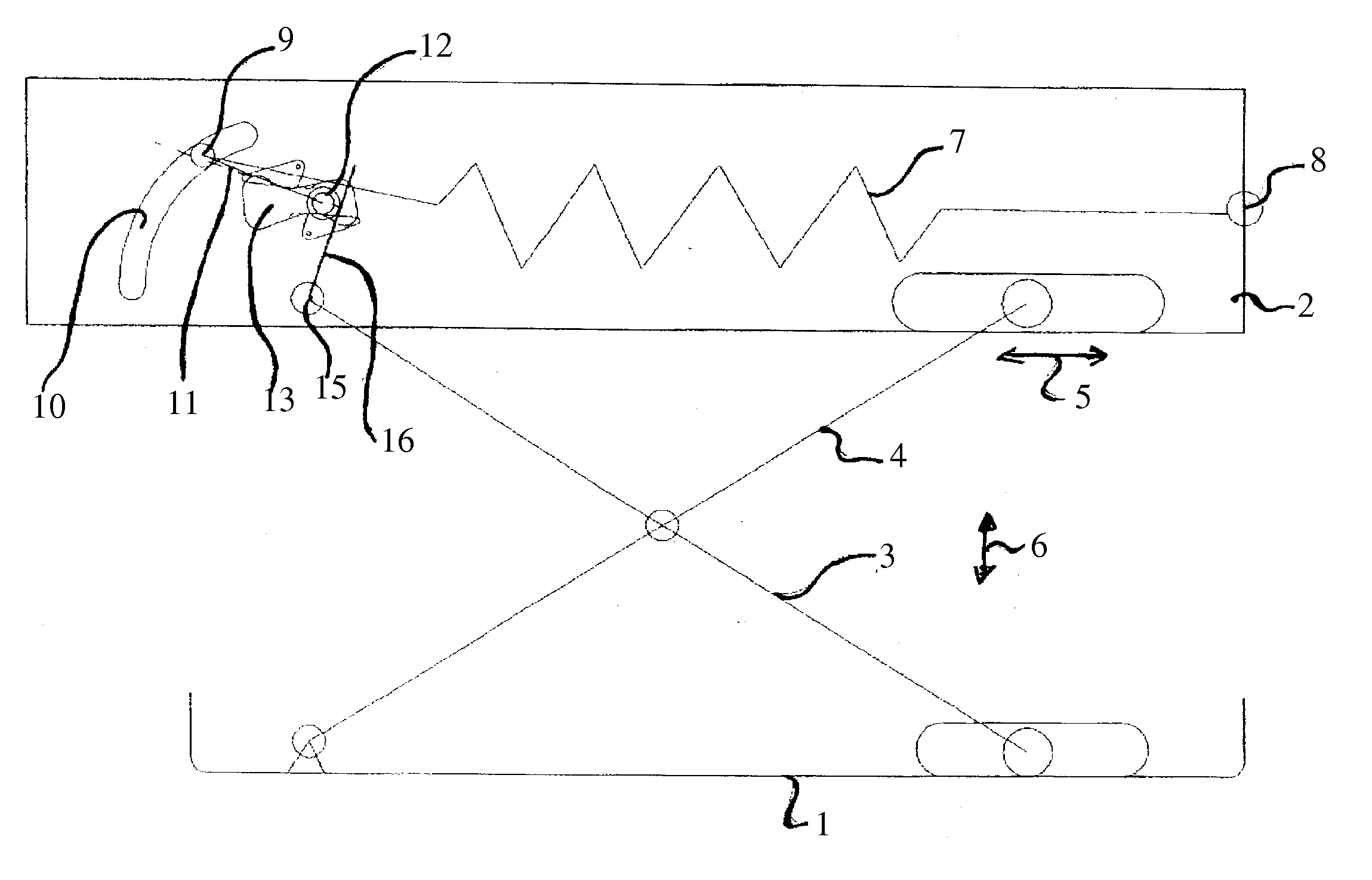
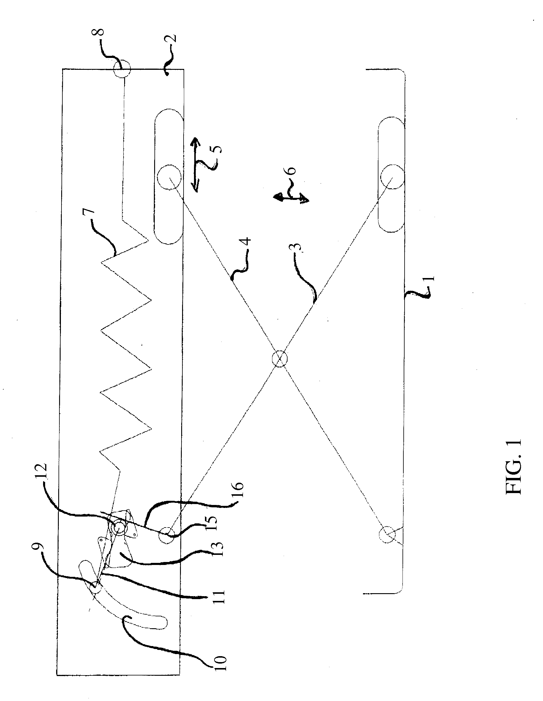
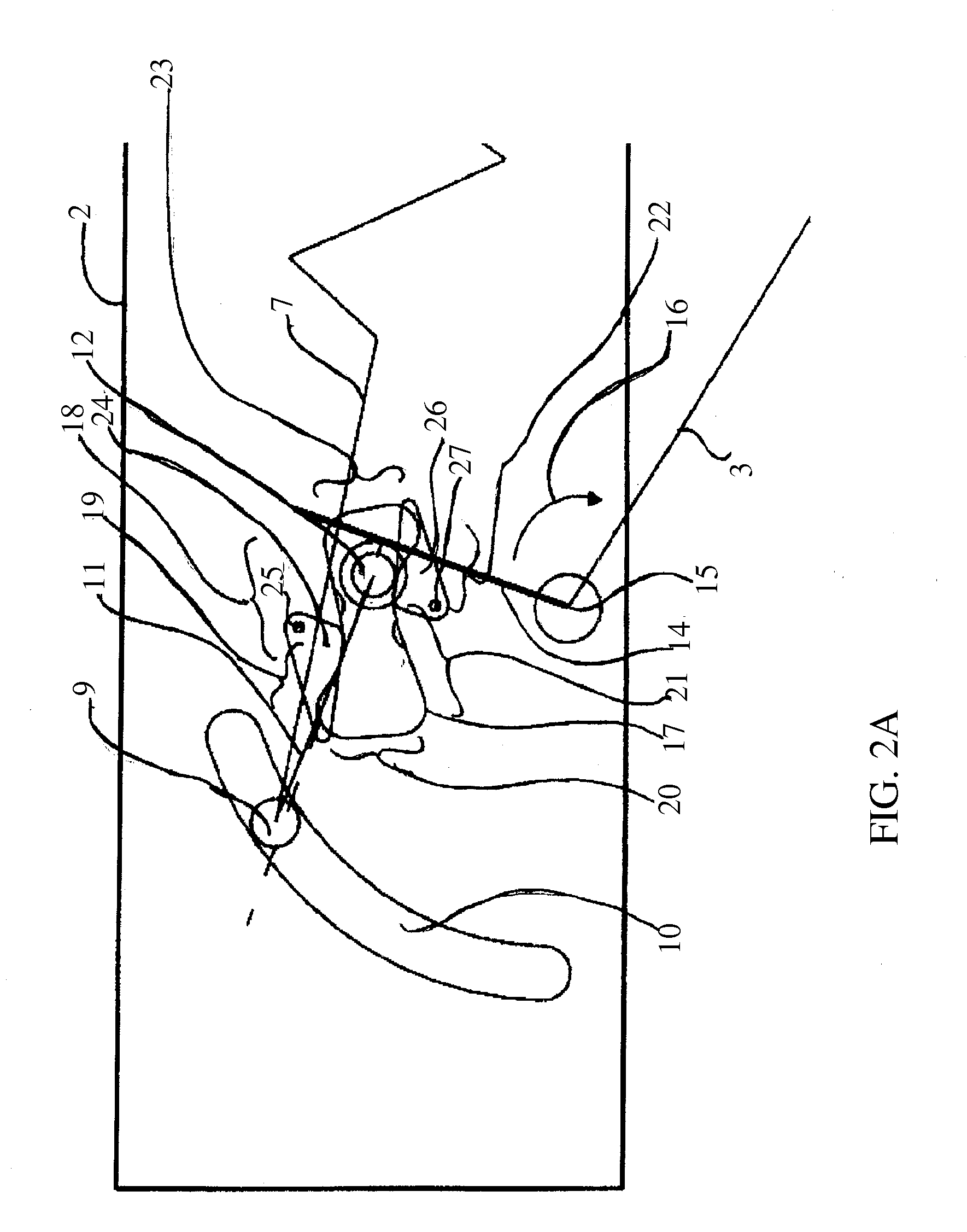
[0030]FIGS. 2a-g show an extract of the spring-mounted vibration system according to the invention as shown in FIG. 1. The section shown here in detail shows the curved linkage path 8 with the guide peg 9 arranged therein and the rod 11. The spring element 7 is also connected with the guide peg 9.
[0031]The travel linkage 13, for a forward vibration movement, has an almost linear first course section 18 and a second course section 19 rising with a first gradient value in relation to the first course section 18. Furthermore the travel linkage 13, along whose edge 17 runs the guide peg or guide roller 12, for the transition from the forward vibration movement to the rearward vibration movement, has a falling third course section 20, the gradient value of which as a second gradient value is greater than the first gradient value.
[0032]In FIG. 2a, the lever arm 14 which is connected with the guide peg 12 and co-determines its deflection, swivels in the direction of arrow 16 because of the...
third embodiment
[0048]FIG. 4 shows a further spring-mounted vibration system according to the invention which can vibrate in the vertical direction along reference numeral 66. Again scissor arms 63, 64 are shown between a spring-mounted lower part 61 and a spring-mounted upper part 62 such as a substructure of a vehicle seat. The swivelling of the scissor arms 63, 64 leads to a shift of the rollers along direction 65.
[0049]A spring element 67 is arranged with one end 68 on the upper spring-mounted part and with a further end 69 arranged by means of guide element inside a curved travel linkage 70. The travel linkage 70 is also arranged inside or connected with the upper spring-mounted part 62.
[0050]A lever arm or swivel arm 74 is mounted swivellably about a rotation point 75 and connected with the scissor arm 64.
[0051]Two damping or springing elements 71 and 72 are arranged on the left and right sides of the swivel arm 74 and on a swivel movement 73 of the lever arm 74 can lead to a damping of the s...
fourth embodiment
[0053]The damper curves of the fourth embodiment shown in FIG. 5 preferably includes the following:
[0054]On compression of the system (to the left or right in the image plane), the dampers or damper elements absorb a low amount of work or energy, i.e. are easy to move.
[0055]On compression of the system the kinetic energy of the sprung mass is largely absorbed by the spring-mounted elements (end position springing).
[0056]On rebound, the damping elements absorb a high amount of work or energy i.e. are difficult to move. On rebound of the system (towards the centre in the image plane), the damping elements absorb a high amount of work or energy so that the stored spring energy is not transferred to the sprung mass again as kinetic energy but absorbed by the damping element.
[0057]On deflection or swivel, the lever arms 84, 85 are damped in their swivel movement by the damper elements 88, 89. This leads to a vibration reduction of the entire vibration system. At the same time the guide p...
PUM
 Abstract
Description
Claims
Application Information
 - Generate Ideas
- Intellectual Property
- Life Sciences
- Materials
- Tech Scout
- Unparalleled Data Quality
- Higher Quality Content
- 60% Fewer Hallucinations
Browse by: Latest US Patents, China's latest patents, Technical Efficacy Thesaurus, Application Domain, Technology Topic, Popular Technical Reports.
© 2025 PatSnap. All rights reserved.Legal|Privacy policy|Modern Slavery Act Transparency Statement|Sitemap|About US| Contact US: help@patsnap.com