Charging control apparatus for electrically powered vehicle, electrically powered vehicle, method for charging control for electrically powered vehicle, and computer-readable recorded medium having program recorded thereon for computer to execute the charging control

a charging control and electric vehicle technology, applied in the direction of electric devices, navigation instruments, external condition input parameters, etc., can solve the problems of increasing the cost of electric power necessary for charging, increasing the cost of electric power storage devices, and increasing the cost of using power storage devices

Active Publication Date: 2010-04-29
TOYOTA JIDOSHA KK
View PDF2 Cites 35 Cited by
  • Summary
  • Abstract
  • Description
  • Claims
  • Application Information

AI Technical Summary

Benefits of technology

[0009]Another object of the present invention is to provide a method for charging control for an electrically powered vehicle that allows a user to select an amount of charge from a power supply outside the vehicle to a power storage device, in consideration of the cost of using the power storage device together with the energy cost, and to provide a computer-readable recording medium having a program recorded thereon for a computer to execute the charging control.
[0025]The present invention thus allows a user to select an amount of charge to be supplied from a power supply outside the vehicle to the power storage device in consideration of the cost of using the power storage device together with the energy cost.

Problems solved by technology

In terms of the cost, while the fuel cost for the engine decreases, the cost for electric power necessary for charging increases and the load resulting from the charging is exerted on the power storage device to cause the power storage device to further degrade.
The cost of using the power storage device therefore relatively increases.
On the contrary, if the amount of charge from the outside of the vehicle is decreased, the fuel consumption of the engine increases, so that the rate of contribution to the environment protection decreases.
In terms of the cost, while the fuel cost for the engine increases, the cost of electric power necessary for charging decreases and the load on the power storage device accordingly decreases.
The cost of using the power storage device is therefore relatively decreases.

Method used


Image

  • Charging control apparatus for electrically powered vehicle, electrically powered vehicle, method for charging control for electrically powered vehicle, and computer-readable recorded medium having program recorded thereon for computer to execute the charging control
  • Charging control apparatus for electrically powered vehicle, electrically powered vehicle, method for charging control for electrically powered vehicle, and computer-readable recorded medium having program recorded thereon for computer to execute the charging control
  • Charging control apparatus for electrically powered vehicle, electrically powered vehicle, method for charging control for electrically powered vehicle, and computer-readable recorded medium having program recorded thereon for computer to execute the charging control

Examples


first embodiment

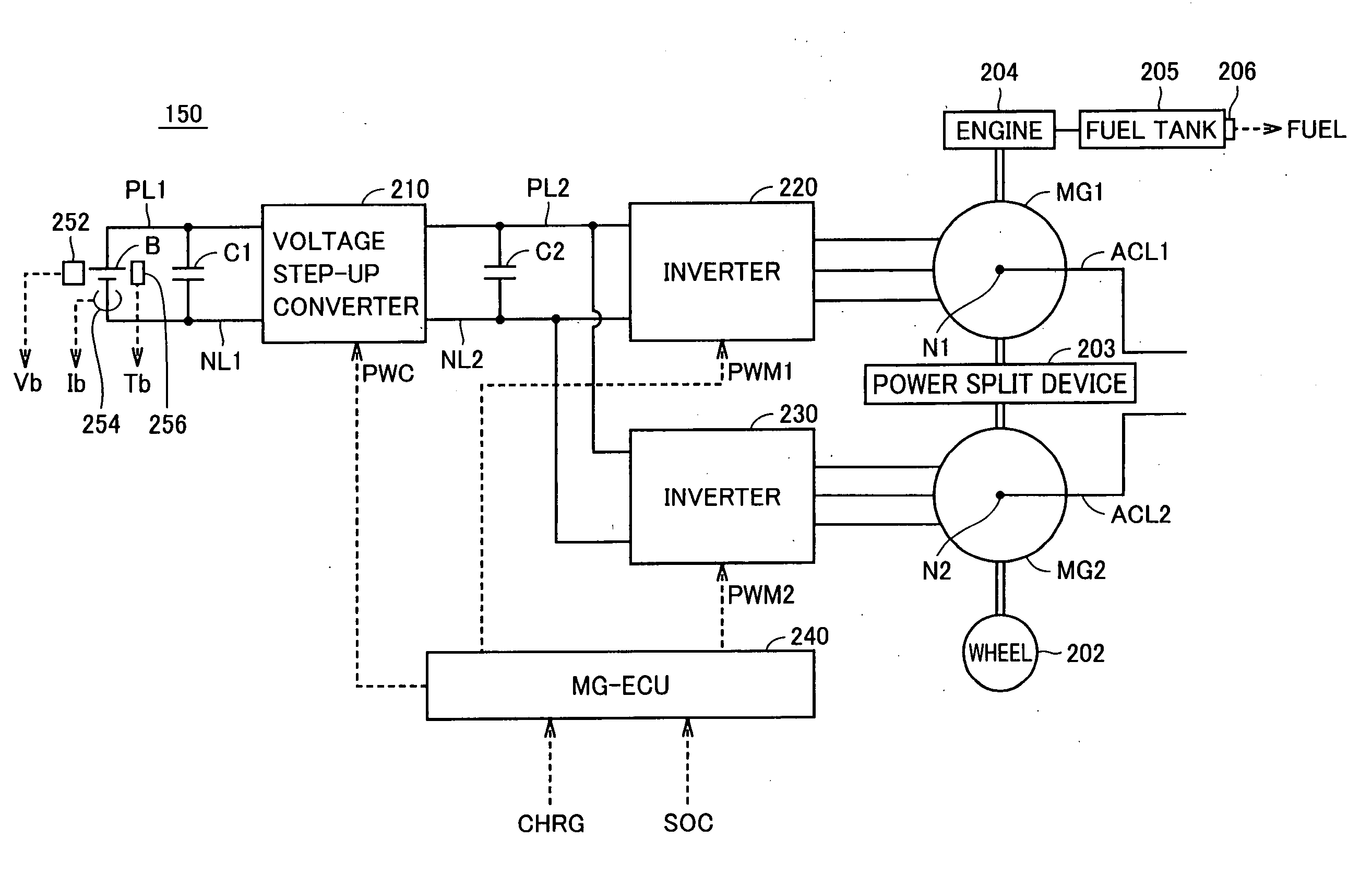
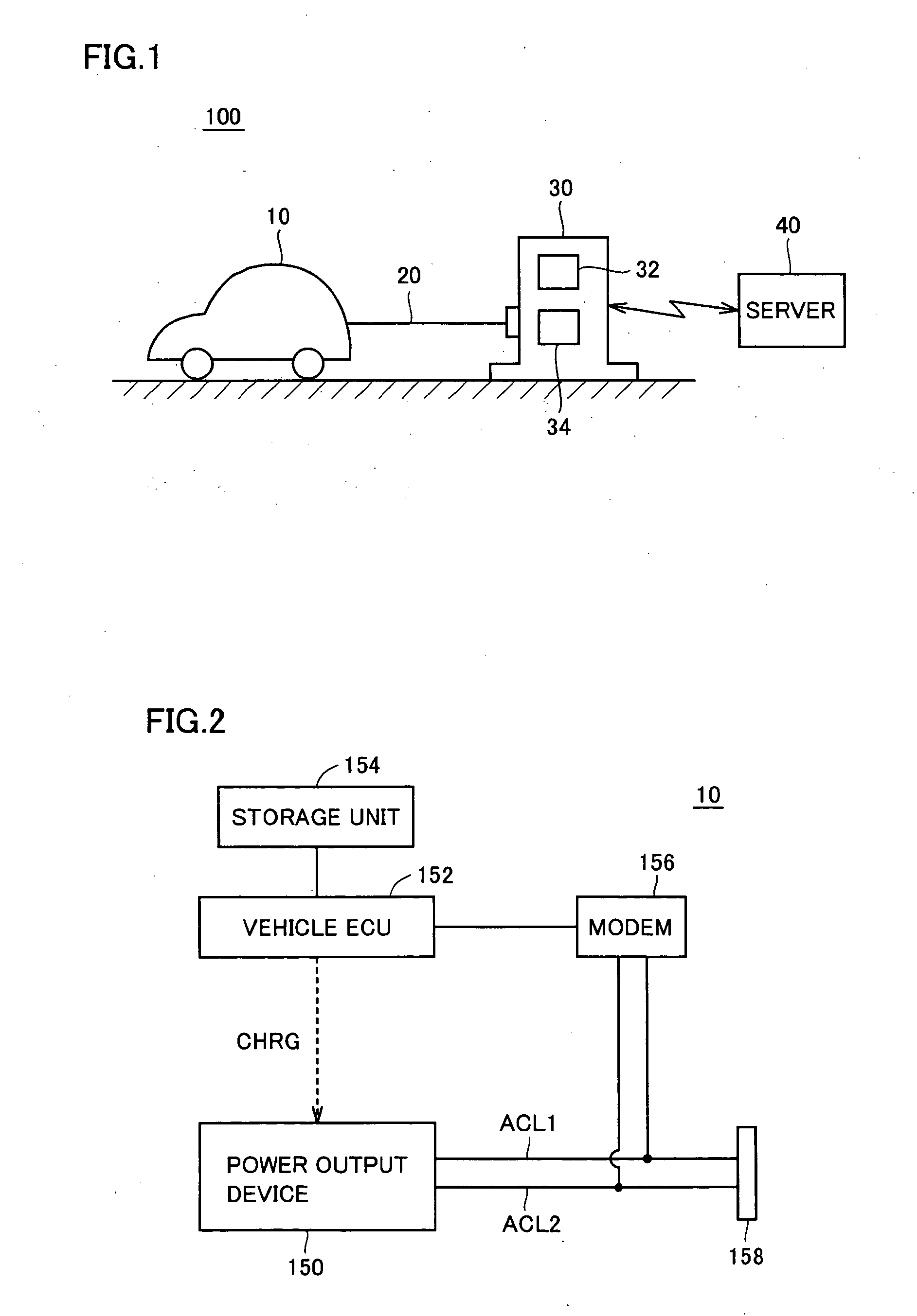
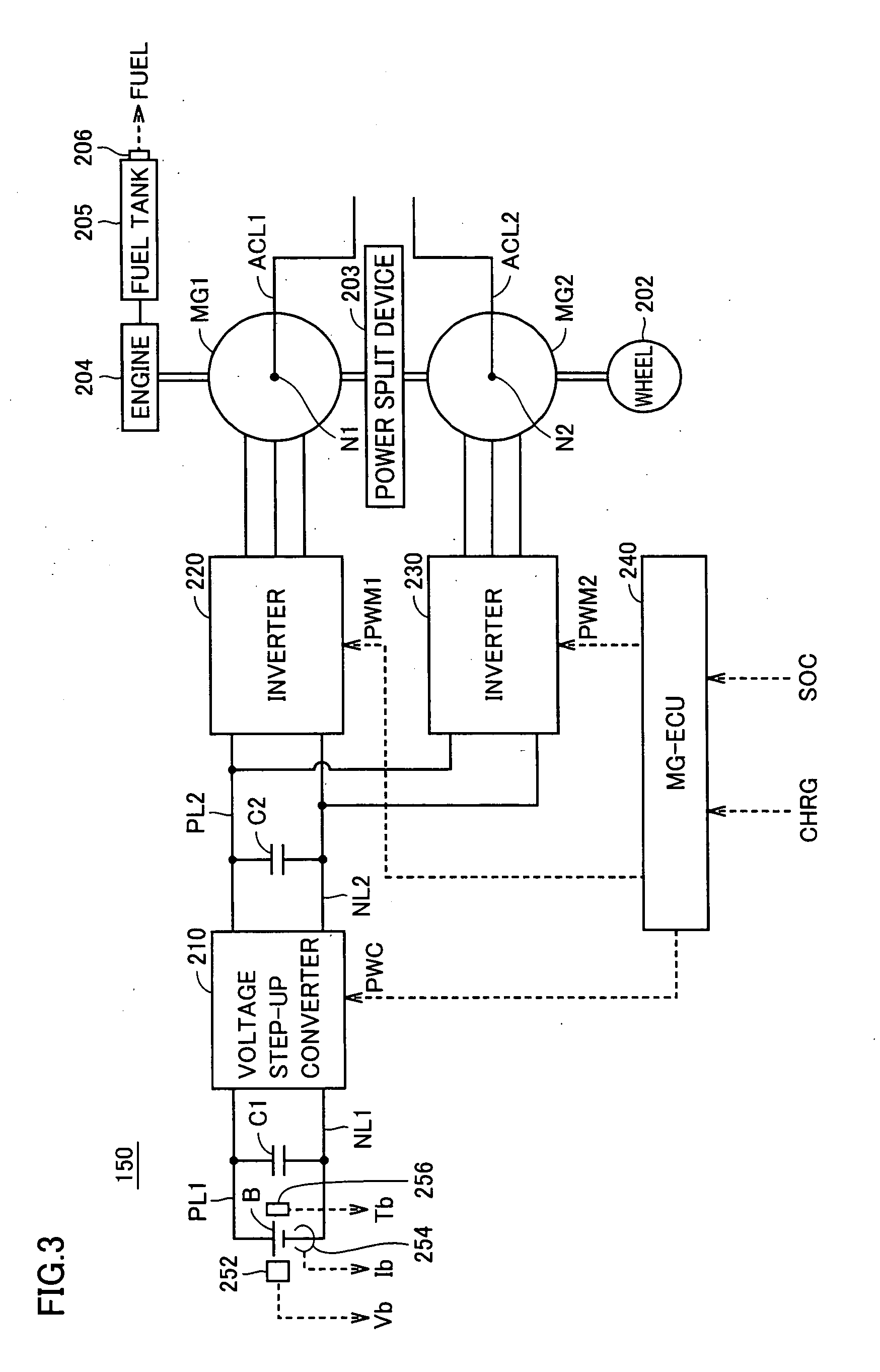
[0047]FIG. 1 is an overall view of a charging control system according to a first embodiment of the present invention. Referring to FIG. 1, charging control system 100 includes a vehicle 10, a charging station 30 and a server 40.

[0048]Vehicle 10 refers to an electrically-powered vehicle configured in such a manner that a power storage device (not shown) mounted on the vehicle is chargeable from a power supply located outside the vehicle, specifically a hybrid vehicle mounted with an electric motor for causing the vehicle to travel, in addition to an engine. Vehicle 10 can be connected to charging station 30 by a connection cable 20, and receives a charging electric power via connection cable 20 from charging station 30. Vehicle 10 also collects and stores travel records during a travel of the vehicle, and outputs the collected travel records via connection cable 20 to charging station 30, before the power storage device is charged from charging station 30.

[0049]Connection cable 20 i...

second embodiment

[0128]In the first embodiment, the energy cost and the cost of using power storage device B are predicted based on travel records in the past. In the present second embodiment, the energy cost and the cost of using power storage device B are predicted based on a travel route that is set by a navigation device of the vehicle.

[0129]FIG. 14 is a schematic configuration diagram of a vehicle in the second embodiment. Referring to FIG. 14, vehicle 10A includes, as compared with the configuration of vehicle 10 in the first embodiment shown in FIG. 2, a navigation device 160 instead of storage unit 154 and includes a vehicle ECU 152A instead of vehicle ECU 152.

[0130]Navigation device 160 is configured to display the present position of the vehicle and to allow a user to set a destination and a travel route to the destination. When a destination is set by a user, navigation device 160 outputs to vehicle ECU 152A the travel route information including items such as the destination, the travel...

third embodiment

[0142]In the present third embodiment, operations performed by charging station 30 in the first embodiment are all performed by the vehicle.

[0143]FIG. 17 is a schematic configuration diagram of a vehicle in the third embodiment. Referring to FIG. 17, as compared with the configuration of vehicle 10 in the first embodiment shown in FIG. 2, vehicle 10B does not include modem 156 but further includes a display device 162, and includes a vehicle ECU 152B instead of vehicle ECU 152.

[0144]Vehicle ECU 152B predicts, for each of a plurality of travel patterns extracted from travel records of vehicle 10B, the energy cost for the next travel of vehicle 10B and the lifetime of power storage device B according to the amount of charge from charging station 30 to power storage device B. Based on the predicted lifetime, vehicle ECU 152B predicts the cost of using power storage device B according to the amount of charge to power storage device B.

[0145]Display device 162 has functions similar to tho...


PUM


Abstract

An energy cost prediction unit predicts an energy cost for the next travel. A lifetime prediction unit uses a charge amount—lifetime map to predict the lifetime of a power storage device according to an amount of charge to the power storage device. A usage cost prediction unit predicts the cost of using the power storage device according to the amount of charge to the power storage device, based on the lifetime of the power storage device predicted by the lifetime prediction unit. The predicted cost associated with the amount of charge to the power storage device is indicated on a display device. In accordance with an instruction from a user, the power storage device is charged from a charging station.

Description

TECHNICAL FIELD [0001]The present invention relates to charging control for an electrically powered vehicle configured in such a manner that a power storage device mounted on the vehicle is chargeable from a power supply located outside the vehicle.BACKGROUND ART [0002]In recent years, the hybrid vehicle has been of interest as an environment-friendly vehicle. The hybrid vehicle is mounted with, in addition to a conventional engine, an electric motor supplied with electric power from a power storage device to generate a drive force for causing the vehicle to travel, and an electrical generator capable of charging the power storage device with electric power generated from an engine output.[0003]A hybrid vehicle mounted with an electrical generator as described above and configured in such a manner that its power storage device is chargeable from a power supply outside the vehicle, like an electric vehicle without being mounted with an engine, is known (see, for example, Japanese Pat...

Claims


Application Information

Patent Timeline
Patent Type & Authority Applications(United States)
IPC IPC(8): H02J7/00B60L50/15B60L50/16
CPCB60K6/445Y02T90/121B60K2001/0455B60L3/0046B60L3/12B60L11/123B60L11/14B60L11/1824B60L11/1838B60L11/184B60L11/1846B60L11/1848B60L15/2045B60L2220/14B60L2230/16B60L2240/72B60L2240/80B60L2250/16B60L2260/54B60L2260/56B60W10/08B60W10/26B60W20/00B60W2540/04G01C21/3469G07F15/005Y02T10/6217Y02T10/6239Y02T10/6269Y02T10/7005Y02T10/7022Y02T10/7077Y02T10/7088Y02T10/7283Y02T10/7291Y02T10/84Y02T90/128Y02T90/14Y02T90/161Y02T90/163Y02T90/169Y04S30/14B60K6/46Y02T10/72B60W2510/248B60L50/61B60L50/16B60L53/60B60L53/64B60L53/65B60L53/665B60L53/305B60W2540/215B60L58/12Y02T10/62Y02T10/70Y02T10/64Y02T10/7072Y02T90/16Y02T90/167Y02T90/12B60W2050/143B60W2050/146B60W50/082B60W50/085B60W2510/244B60W20/12B60W2556/50
Inventor UCHIDA, MASATOSHI
Owner TOYOTA JIDOSHA KK
Why Eureka
Try Eureka