Method of transmitting sounding reference signal

a reference signal and signal transmission technology, applied in the field of wireless communication, can solve problems such as difficulty in preserving single carrier characteristics, and achieve the effect of preserving the single carrier characteristics required in uplink transmission

Active Publication Date: 2010-04-29
LG ELECTRONICS INC
View PDF99 Cites 173 Cited by
  • Summary
  • Abstract
  • Description
  • Claims
  • Application Information

AI Technical Summary

Benefits of technology

[0012]According to the present invention, multiplexing can be achieved without collision between data and a sounding reference signal by using a sounding indicator. In addition, multiplexing can be achieved without collision between a control signal and the sounding reference signal by using a simultaneous transmission indicator. Therefore, single carrier characteristics required in uplink transmission can be preserved.

Problems solved by technology

Therefore, when the SRS is transmitted simultaneously with other uplink control channel or uplink data, it is difficult to preserve the single carrier characteristics.

Method used


Image

  • Method of transmitting sounding reference signal
  • Method of transmitting sounding reference signal
  • Method of transmitting sounding reference signal

Examples


Embodiment Construction

[0022]In the following descriptions, a downlink represents a communication link from a base station (BS) to a user equipment (UE), and an uplink represents a communication link from the UE to the BS. In downlink, a transmitter may be a part of the BS, and a receiver may be a part of the UE. In uplink, the transmitter may be a part of the UE, and the receiver may be a part of the BS. The UE may be fixed or mobile, and may be referred to as another terminology, such as a mobile station (MS), a user terminal (UT), a subscriber station (SS), a wireless device, etc. The BS is generally a fixed station that communicates with the UE and may be referred to as another terminology, such as a node-B, a base transceiver system (BTS), an access point, etc. There are one or more cells within the coverage of the BS.

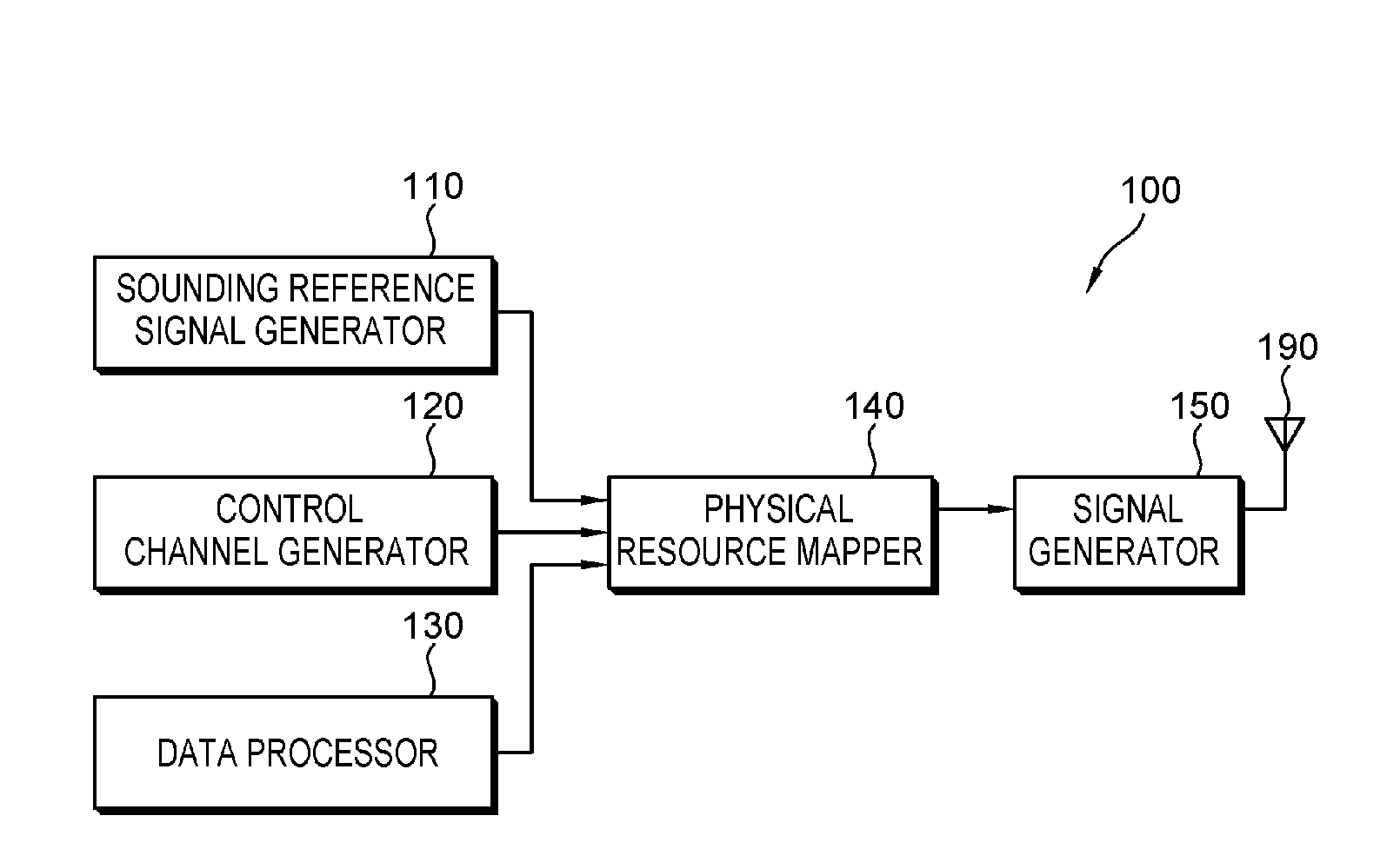
[0023]FIG. 1 is a block diagram of a transmitter according to an embodiment of the present invention.

[0024]Referring to FIG. 1, a transmitter 100 includes a sounding reference signal ge...


PUM


Abstract

A method of transmitting a sounding reference signal (SRS) includes receiving SRS operation information including a sounding indicator, the sounding indicator indicating whether SRS transmission takes place at a subframe; generating the SRS according to the SRS operation information, and if the sounding indicator indicates occurrence of SRS transmission, transmitting the SRS at the subframe. Multiplexing can be achieved without collision between data and a sounding reference signal and single carrier characteristics required in uplink transmission can be preserved.

Description

TECHNICAL FIELD[0001]The present invention relates to wireless communications, and more particularly, to a method of transmitting a sounding reference signal.BACKGROUND ART[0002]In next generation wireless communication systems, multimedia data can be transmitted with high quality at a high speed by using limited radio resources. To achieve this, a spectral efficiency has to be maximized since a radio channel has a limited bandwidth. In addition, inter-symbol interference and frequency selective fading, which occur during high-speed transmission, have to be overcome.[0003]In order to improve performance of the wireless communication system, a closed-loop transmission scheme using a channel condition between a base station (BS) and a user equipment (UE) has been introduced. An adaptive modulation and coding (AMC) scheme is used to improve link performance. In the AMC scheme, the BS controls a modulation and coding scheme (MCS) by using feedback of channel condition information.[0004]...

Claims


Application Information

Patent Timeline
Patent Type & Authority Applications(United States)
IPC IPC(8): H04W4/00H04B7/208H04L12/16
CPCH04L5/0007H04L5/0048H04L5/0055H04L5/0082H04L5/0053
Inventor KIM, HAK SEONGKIM, BONG HOEYUN, YOUNG WOO
Owner LG ELECTRONICS INC
Why Eureka
Try Eureka