
Signal transmitting device for drums

a signal transmitting device and drum technology, applied in the field of wireless signal transmitting devices, can solve the problems of time-consuming and complex wiring, and the inability to carry around the drum, and achieve the effect of significantly simplifying the complex wiring process

Inactive Publication Date: 2010-04-29
HSIEN CHAO YING
View PDF5 Cites 14 Cited by
  • Summary
  • Abstract
  • Description
  • Claims
  • Application Information

AI Technical Summary

Benefits of technology

"The present invention is a wireless signal transmitting device for drums. It includes multiple drums with pickups and wireless signal transceivers, and a sound module with wireless signal receivers that correspond to the drums. When the drum is beaten, the pickup sends a signal to the wireless signal transceiver, which then sends it wirelessly to the corresponding wireless signal receiver on the sound module. This simplifies or eliminates the complex wiring process. The technical effect of this invention is to provide a more efficient and simplified way to transmit signals from drums to a sound module."

Problems solved by technology

However, this transmitting method leads to time-consuming and complex wiring, especially for jazz performance with multiple drums and other percussion instruments.
Besides, this method also arises another problem that it is almost impossible to carry about the drum during the military music performance, since the wires will greatly influence the parade of the players.

Method used


Image

  • Signal transmitting device for drums
  • Signal transmitting device for drums
  • Signal transmitting device for drums

Examples


first embodiment

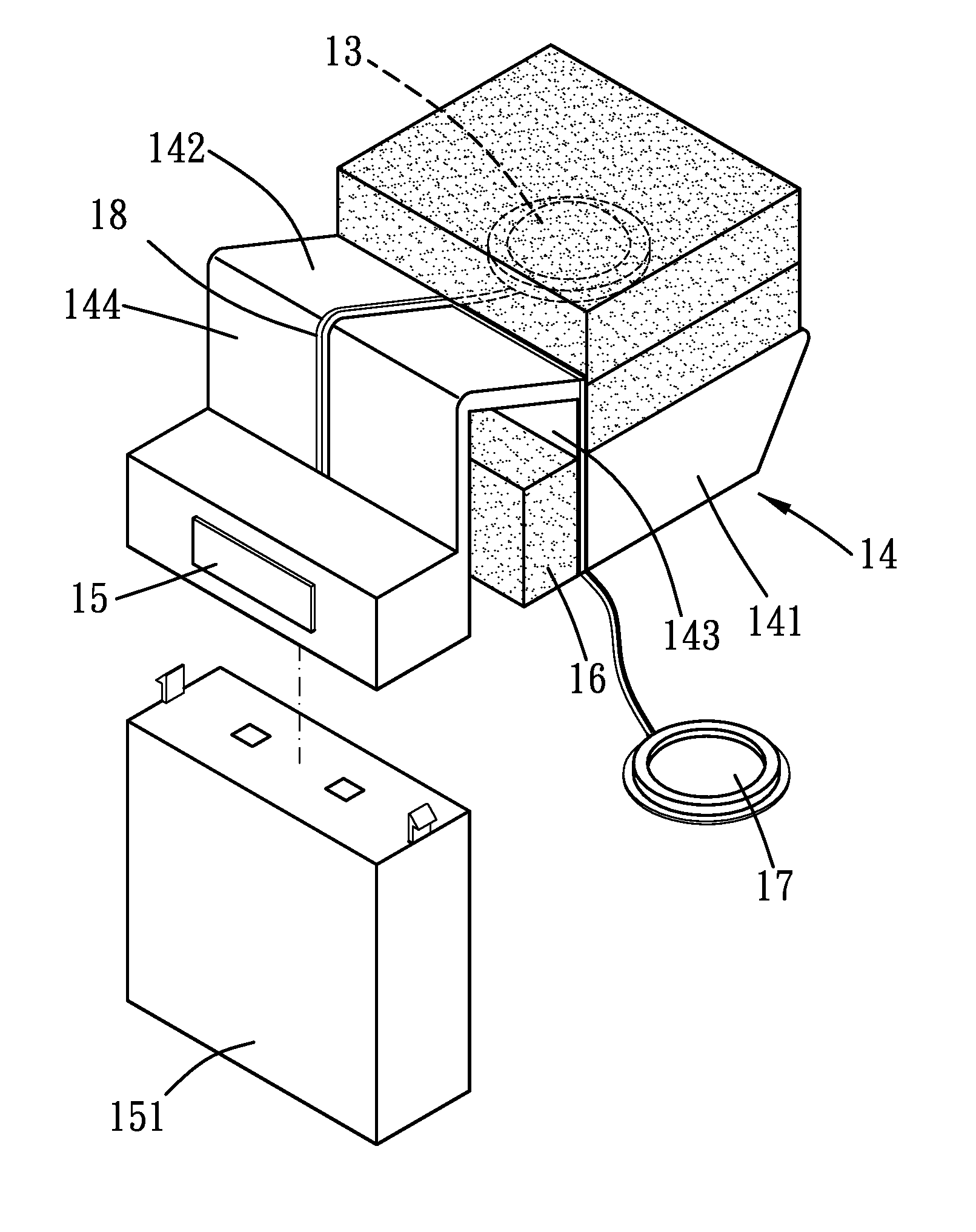
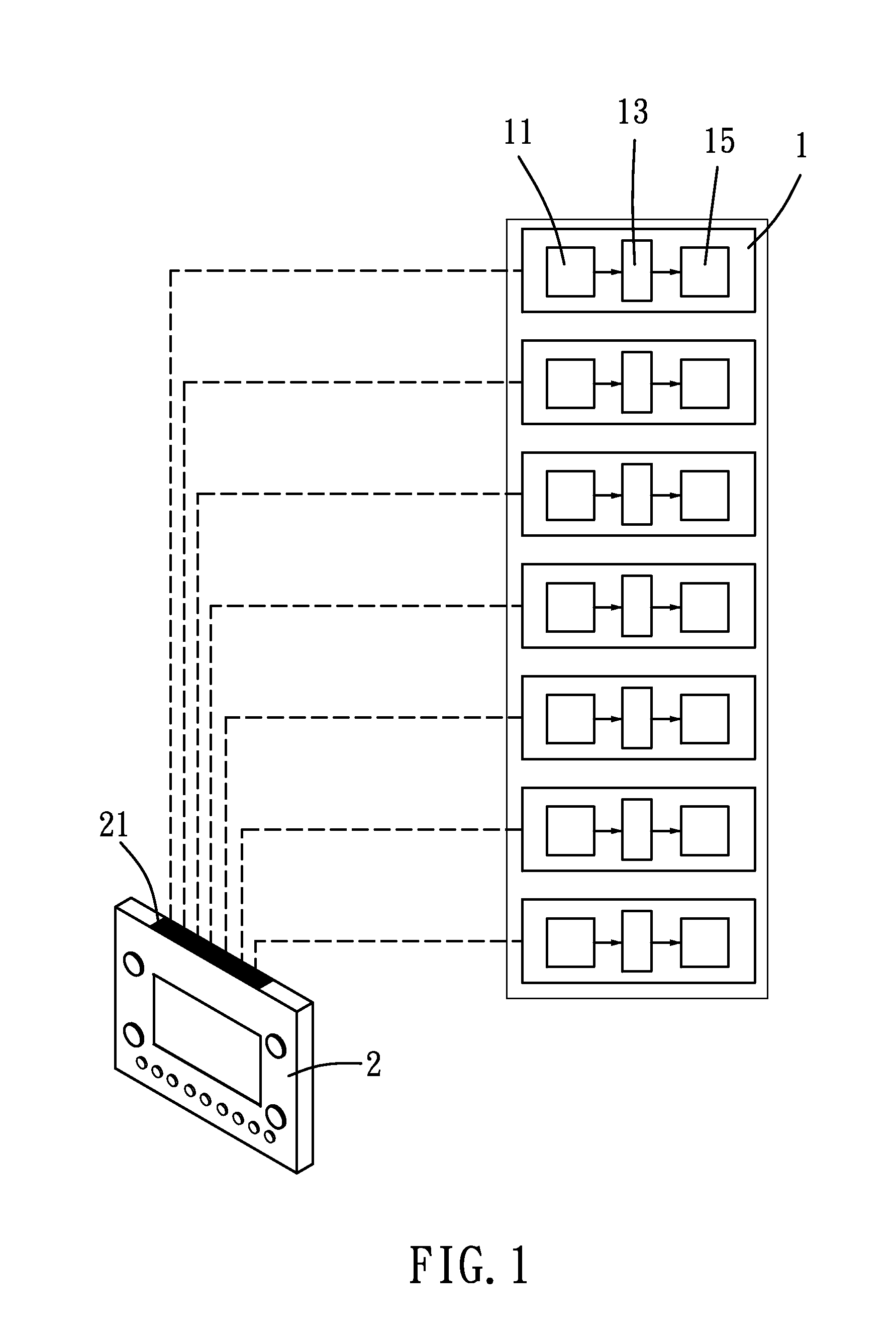
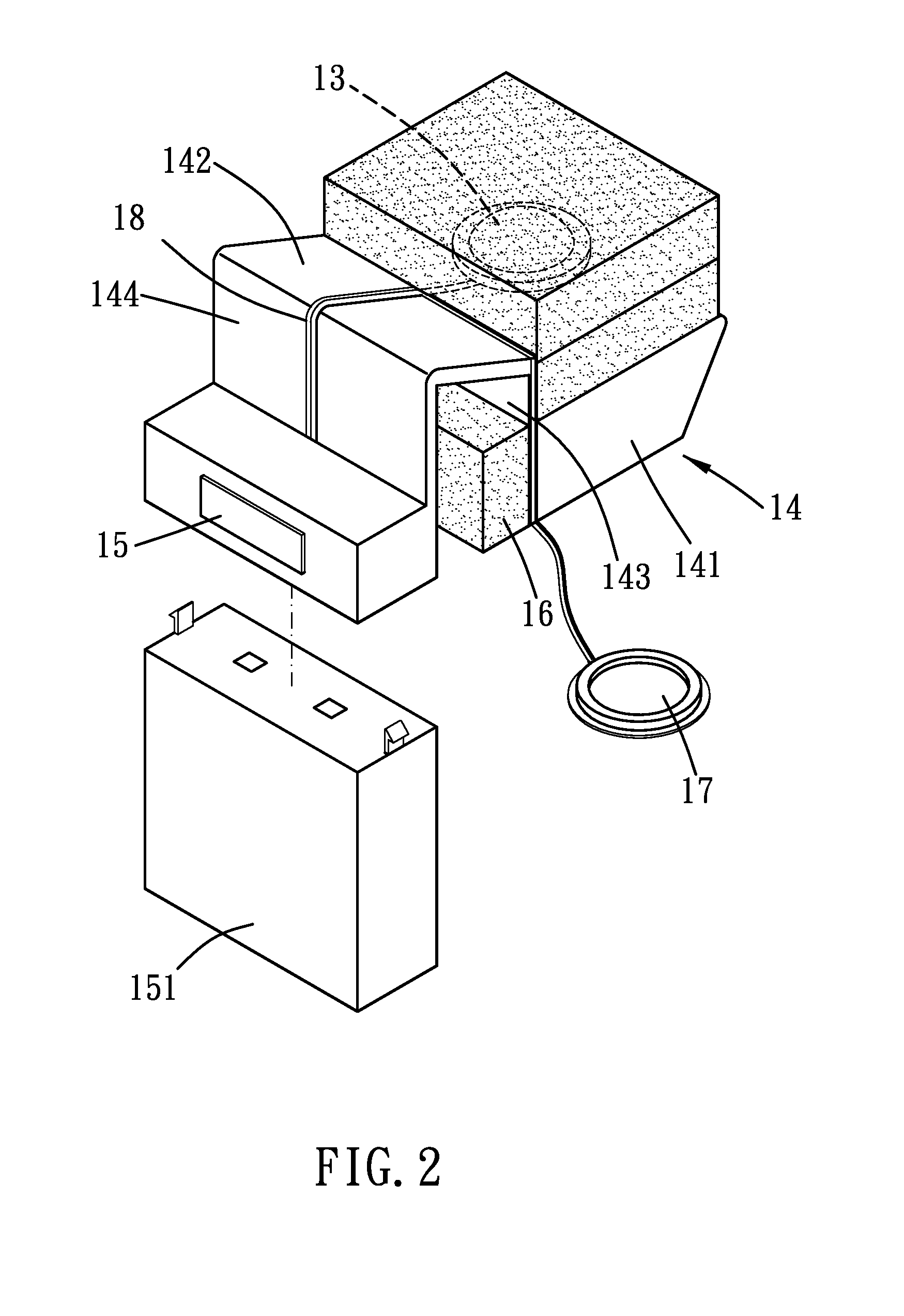
[0015]Please refer to FIG. 1 to 5 for the present invention. A signal transmitting device includes a plurality of drums 1 and a sound module 2. Each drum 1 has a drum tympan 11 to be beaten upon and a drum rim 12. The drum rim 12 is cylindrical and has at least one opening on one side thereof, and the drum tympan 11 envelops the opening. The drum tympan 11 is made of materials that make sounds upon beaten, or it can be made of a muffle material that makes little sound while beaten, which is common seen in electronic drums. In addition, the sound module 2 can process beating signals and then transfers the signals into audio signals, which is to be broadcasted by a speaker. The sound module 2 has at least one wireless signal receiver 21.

[0016]Each drum 1 has a pickup 13, a supporting seat 14 and a wireless signal transceiver 15. The supporting seat 14 includes a supporting portion 141 and a positioning portion 142. The pickup 13 is disposed on the supporting portion 141, and the posit...

second embodiment

[0019]Please refer to FIG. 6. In the present invention, the sound module 2 includes two wireless signal receivers 21 to increase the transmitting efficiency. That is to say, each receiver 21 corresponds to only part of the transceivers 15. Preferably, each receiver 21 corresponds to just one of the transceiver 15, thus preventing audio delay or distortion resulting from signal interference.

[0020]The signal transmitting device of the present invention prevents the complex wiring between the sound module and the drums, and it will no longer influence the parade or formation change of a military music performance. Furthermore, the pickup of the present invention is disposed close to the periphery of the drum tympan rather than the center thereof, such that the pickup just interferes the vibration of the tympan slightly yet still directly contacts the tympan to ensure the beating signal undistorted. In addition, the first and second sections of the supporting seat tightly clamp the drum...


PUM


Abstract

A signal transmitting device of the present invention includes a plurality of drums and a sound module. Each drum has a pickup and a wireless signal transceiver, and the sound module includes several wireless signal receivers, each of which corresponds to one of the drums. While the drum is beaten upon, the pickup sends a signal to the wireless signal transceiver, and the signal is then transmitted to the corresponding wireless signal receiver wirelessly. Thereby, the complex wiring process can be significantly simplified or even totally resolved.

Description

BACKGROUND OF THE INVENTION[0001]1. Field of the Invention[0002]This is a CIP of application Ser. No. 12 / 256,479, filed Oct. 23, 2008. The present invention relates to a wireless signal transmitting device between drums and a sound module.[0003]2. Description of the Prior Art[0004]A conventional pickup of a drum transmits a signal to a sound module by wires. However, this transmitting method leads to time-consuming and complex wiring, especially for jazz performance with multiple drums and other percussion instruments. Besides, this method also arises another problem that it is almost impossible to carry about the drum during the military music performance, since the wires will greatly influence the parade of the players.SUMMARY OF THE INVENTION[0005]The main object of the present invention is to provide a wireless signal transmitting device for drums.[0006]To achieve the above object, a signal transmitting device of the present invention includes a plurality of drums and a sound mo...

Claims


Application Information

Patent Timeline
Patent Type & Authority Applications(United States)
IPC IPC(8): H04B7/00
CPCG10H2240/211G10H3/146
Inventor HSIEN, CHAO-YING
Owner HSIEN CHAO YING
Learn More